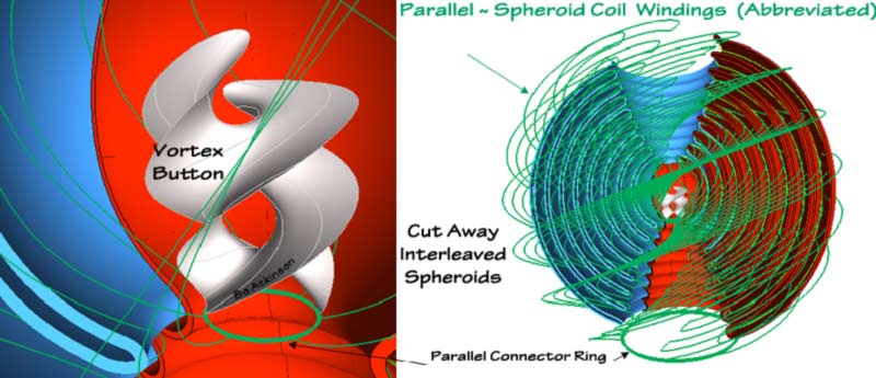
The inner electrode can connect through a core surface foil or through a wire, or through a pair of paths instead of one path. Use of the pictured sphere or of hyperboloid- cones, or of a plain cylindrical form provide a good number of experimental paths to separately try. These variables each can provide vortex shaping. Shaped and segmented vortices are expected to provide useful, new effects, to experiment with.
A variety of terms like: spark gap, electrode, cathode , anode, antenna, contact and even button, have been used to describe energized terminals. My work has been limited to feeble electronic apparatus and cheap tools, (besides my decades of other obligations). It is only flashes of inspirations from great works of Tesla and others, who spur me to imagine energetic geometry.
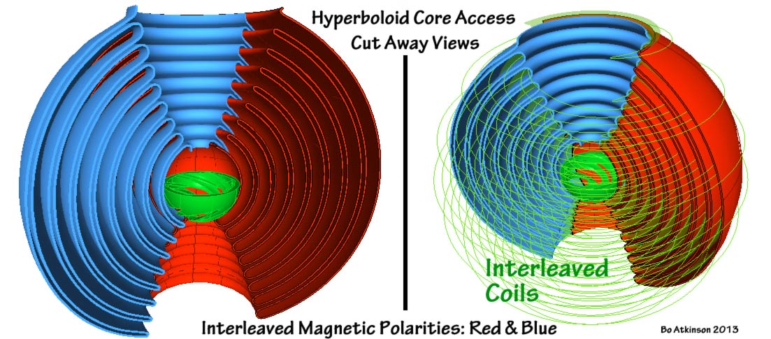
Multiple details are listed in no particular order. The red and blue interleaved brims must be blocked at one end and exposed at the other end. In case wire-coils are used, a tight concentration of coil wires are suggested to enhance the inverse field effect. As neighboring concentric fields will be inverted, (from layer to layer). A tight wire concentration at the brim, should segregate magnetic fields and avoid inter-layer leakage.
'Brim' arrangements are stressed in that these should confine and specifically direct the magnetic fields to opposite ends of the core. My construction concepts vary at this point. Wires are one approach and conductive sheathing is another approach. In fact use of uninsulated wire (EG tin coated copper) can form a "conductive sheath". In that the shortest conductive path may thus occur across the wire diameters. Except that electrical-contact may likely prove to be inconsistent or difficult to perfect. Exploratory efforts will be detailed later. Next below are diagonally wound 'windings'.
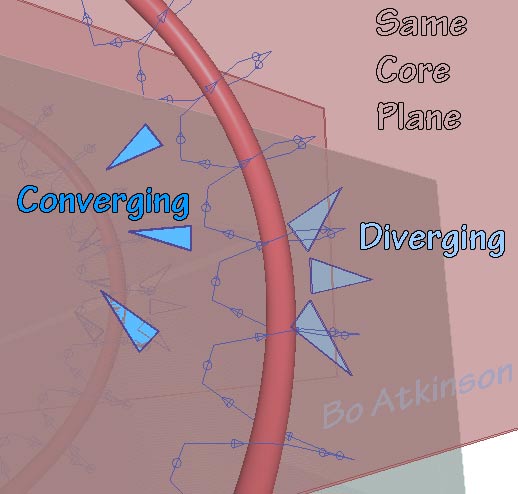
Diagonal alignment with coil axis imparts a cork screw or rifling effect. The geometry shows that opposing magnetic fields can interleave concentrically. Interleaving conductive paths induce opposite magnetic alignments to either side of conductor. In these images, the electrical paths are parallel paths. Illustration of winding methods for these coils, will be provided here, as time permits it.
Skipping over, from compound curved inductors, i will add some planar, or rolled up coils, next below. Planar or flat sheet material is readily available to build cylindrical coils. Flexible PCBs with segregated or etched electrical paths could provide a ready production method. When rolled into a coil, the consequential magnetic paths will spin magnetic vortex fields. Cylindrical segments are suggested below, with parallel connections at either end.
Cylinders of printed coils may be nested together. Parallel end connections should have been included in the images! (Please bear with this.) Two adjacent ends could electrically connect with simple crimping or soldering. Alternating end connections will result in the reflexing coil arrangement. Meaning that each nested cylinder would connect serially with the neighboring cylinder.
Besides nesting cylinders, the rolled up, laminated coil configuration would connect all the diagonal paths in one parallel path set.
Continuation of my printed coil "thought experiments", March 2013, modeling for a transversely wound and folded coil.
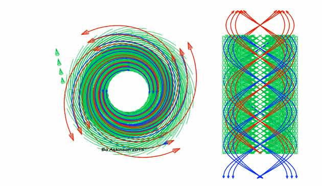
Next Image Below - To Left: A perspective view of cylindrical coil fields. To Right: An axonometric or non-perspective side view of the same cylindrical coil fields.
My initial effort to study physical modeling of these concepts is here. Click to see the larger image.
For me another aspect of great interest in these coils is the "unsymmetrical profile" to be noted with specially aligned view angles, such as the portion of above image marked "Perspective Angle" This is explained in more detail here. Could this some how harness an etheric "turbine effect"? As in the suppressed, alternative sciences.
This page will be continued, as time permits.
Envisaging Transverse Force Fields: Laminated, parallel coils are considered on this linked page.
My earliest work with reflex-vortex amplification through interleaved layering is here.
Pictorial, Partial, Index Page
My earliest work with 3D modeling software.
My exploration of electric and magnetic field relationships, through geometry.
My 1980 experiments with feable currents and coil geometries.
"Vortex-Flame-Amplifier"
"Spinductor"
"Morphing-Sphere Spiral"
"Reflex Flame Amplifier"
"Spherical Reflex Coil"
"Plasma Resonator"
"Reflex Vortex Amplifier"
"Multi Axial Coils"
~~~~~~~~~~~~
![]()
Note: My 100s of pages on this website, http://harmoniouspalette.com, are placed in the The content on this website, http://harmoniouspalette.com, is placed in the public domain only as a free exchange of ideas and as a "hard studied wish to serve life". The author assumes no responsibility for the improper use of the concepts in these web pages. All relevant laws of life and local codes should be verified and observed before any building or experimentation proceeds. discussion is welcome, please write. Bo Atkinson and are furnished "as is" and "open source". My creativity is posted as a free exchange of ideas and as my "service to others". Caution: The author assumes no responsibility for the improper use or improper misuse of the concepts in these web pages. All relevant laws of life and local codes should be verified and observed before any building or experimentation proceeds. Donations to me would be welcome, for me to continue or to up step the progress of these works. Cooperation might be possible as well, please write. Bo Atkinson
~~~~~~~~~~~~
.