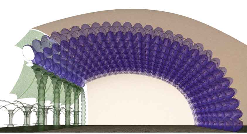
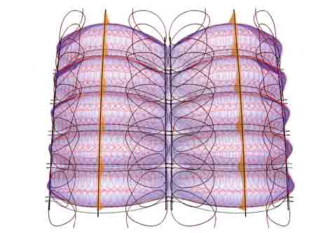
Above is a view from the narrow end of a conceptual vault, roughly 65'X100' or 20X30 meters. Height is roughly two or more stories. To left is shown an arbor concept for growing shade vines for summer shading and winter sun gain to vault space. Colder climates would better consider placing the upper vines inside the vault. Thus, solar gain could continue year round while foliage filtered light is provided to ground floor. Engineering should take local climate into consideration, (as well as to clarify all design aspects). Some sort of glazing system covers the green colored arch area. The tan arch above signifies a large mass of soil covering the entire structure to absorb heat and thereby stabilize temperature year round. .The blue is the focus of this page. It is a thin shell ferrocement grid work of arched coffers. A substantial surface area is presented by coffers which complement PAHS objectives.
The content on this website, http://harmoniouspalette.com, is placed in the public domain only as a free exchange of ideas and as a "hard studied wish to serve life". The author assumes no responsibility for the improper use of the concepts in these web pages, as all relevant laws of life and local codes should be verified and observed before any building or experimentation proceeds. discussion is welcome, please write. Bo Atkinson
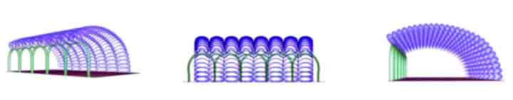
Following are scalloping coffer/ purlins, which when ganged together make up the vault.
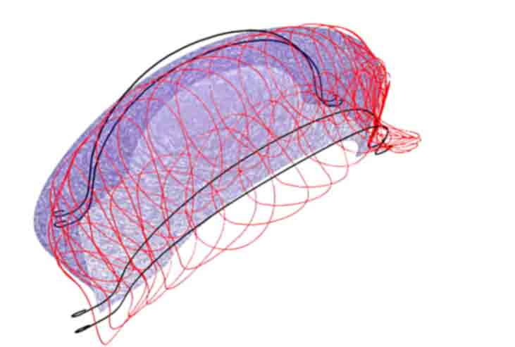
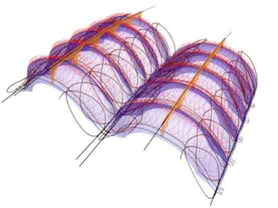
Each rounded coffer integrates the ferrocement shell together with the purlin member, all as one entity. These rounded coffers are easily molded on arrays of inner tubes which are supported temporarily. Wire rings or "flat spirals" are used for reinforcement, (red). Heavier and straighter stock is shown along the junctures.
The rings overlap. Schematic portrayal does not necessarily represent the actual ring diameters. More links about rings will be added as time permits. Rigs to easily place wires in wet cement is presently under development.The large wires represent a "backbone juncture" to hold the "purlin/ ribs". The 3D contours embody the structural grid work
Black rings above portray a truss like layout of undulating rings. The truss itself undulates, following the scalloping contours. Heavier bars are represented by the straighter black lines in the picture below.The outermost edges of the truss ride on the top of the coffers and the inner edge of the truss at the backbone juncture. This explores ferrocement design methods to integrate truss work and ceilings in one unified component. Computer models are available and offered free for the purpose of engineering analysis.
![]()
The content on this website, http://harmoniouspalette.com, is placed in the public domain only as a free exchange of ideas and as a "hard studied wish to serve life". The author assumes no responsibility for the improper use of the concepts in these web pages, as all relevant laws of life and local codes should be verified and observed before any building or experimentation proceeds. discussion is welcome, please write. Bo Atkinson