Cadmera
A Continuing Thought Experiment
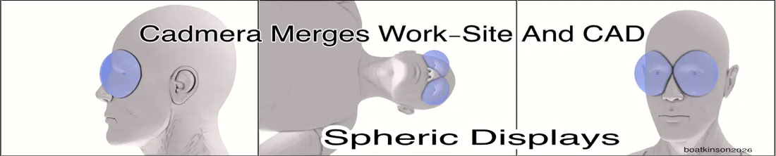
A 2026 concept of centered, spherical VR goggles adds further concepts to the original 2004 concept.
Eyeball centers align with a bi-spheric-VR-screen for optimal, dually traceable vision, which integrates CAD models with real world vision. Fully reversible inputs and outputs align the real world with the VR world to prioritize mensuration, coordinate marking, recording and retrieving of developing data, both in real life and in the CAD app of an individual’s choice.
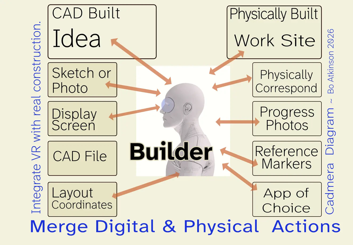
An integration of video tools and graphical-engineering-immersion into physical work spaces of structuring processes. Initially conceived of as a concrete molding process guided directly from 3d models on a building-site or workbench to control a live, additive build activity enabling free hand guidance, along with full access to pertaining details during the process, along with other, future supportive features of the future.
Experimentation and Implementation
Updates of 2008
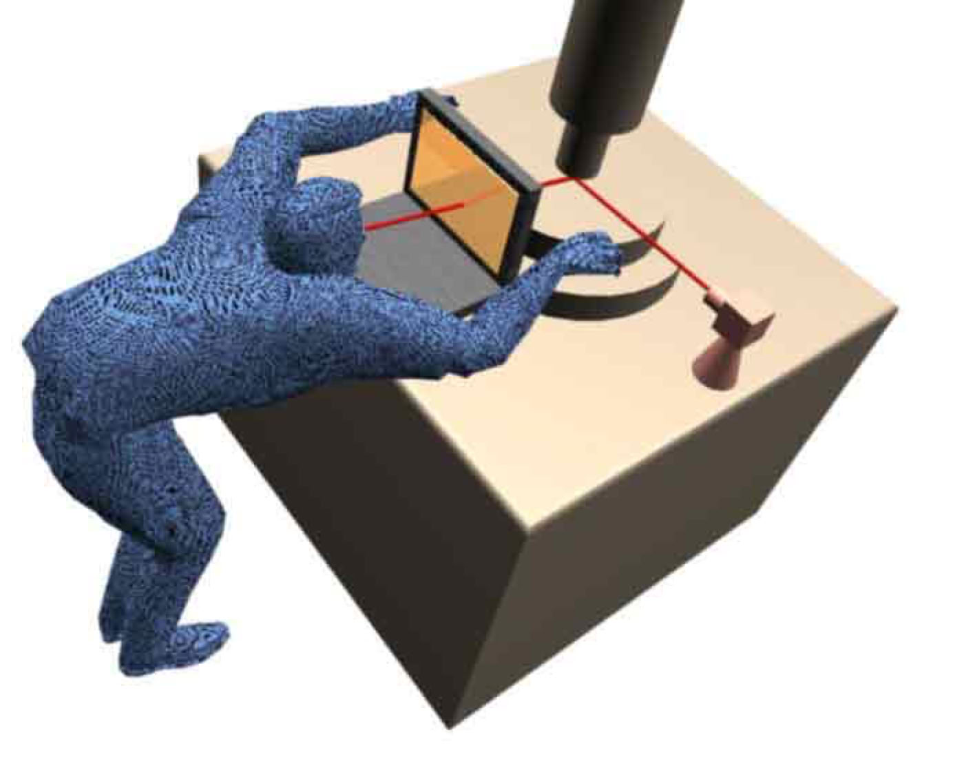
Earlier accumulated notes follow below:Live video of a work space could one day replace the measuring tape and all kinds of layout tools. The antique trade secret known as "Camera Lucida" is employed with modern 3D CAD. Ideally a builder would have goggles with video access to both strategically placed cameras of work scene and to the actual computer interface of a 3D work plan, which would vary according to the work project and could take forms. Illustrated for the era of early personal-computers, this page presents ongoing research into direct use of personal computers in construction and fabrication work-- Ultimately, very compact equipment could evolve and perhaps apply to any kind of physical labor which uses measuring devices or patterns. Future equipment will be much easier to use than the experimental research presented here.
Artistic architecture is most in need of the currently implemented Cadmera methods. (Examples can be found here). A good brand of CAD software works as the lay-out and measuring tool for concrete, carpentry and other kinds of live work. An organic style of architecture is demonstrated here. The first picture depicts a make-shift method to use a generic PC, strapped to a user. Gaming goggles might work more conveniently if the resolution is high enough along with smaller PCs even the present MacMini.
Formatting and updates of the old website is in progress when priorities call.
This page retains earlier Cadmera development history below, to show the progress of this research. Therefore the presentation will be a little crude. I've not gotten around to mocking up more ideal builder-equipment than the illustration above but do intend to. Latest News Flash-- Here is another great lens released late in 06. A great super-wide angle lens which produces pictures without distortion. I'm not sure if a single definitive name was given to the lens unit, but it seems primarily destined for manufacturers of security systems. ZD net may still have a fairly concise article--
http://bacteriologists/emerging tech/index.php?p=425
The source for the lens--
http://www.nanophotonics.co.kr/html_shop/en_shop_list.htm
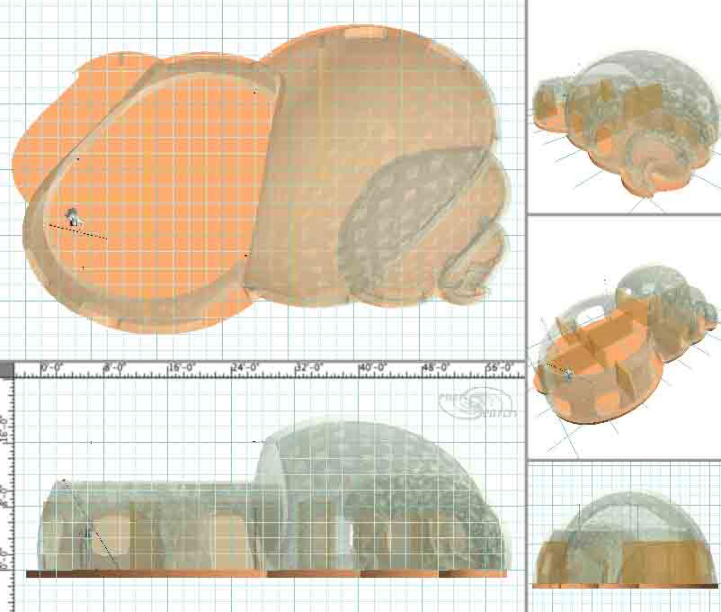
The next picture shows a popular natural shape modeled in 3D CAD, followed by general procedures to build it in real life.
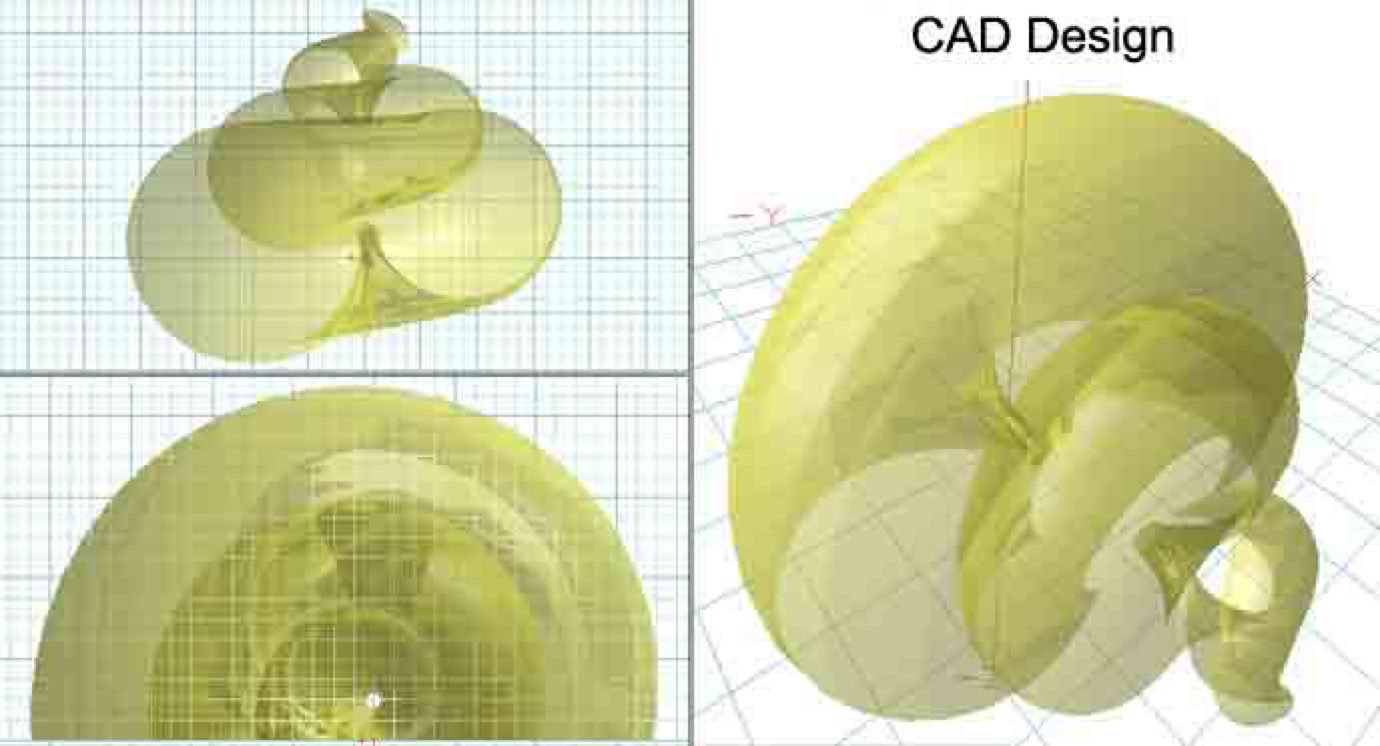
Next is shown a CAD design adaptation using the same shell for a house. Semi-transparent rendering intends to provide abbreviated clarity.
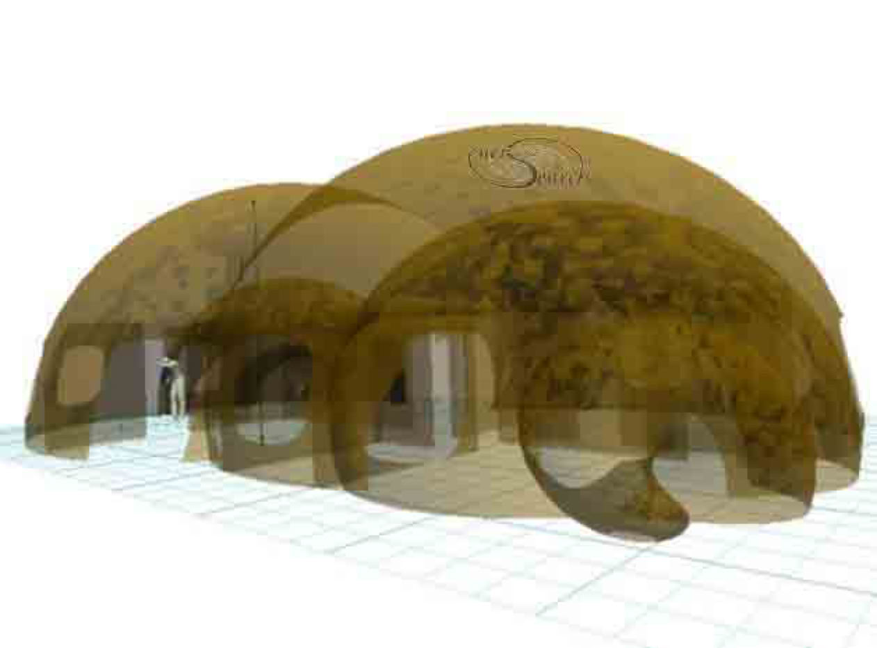
The same CAD model continues below. It is rendered "in the rough", saved in extra-low resolution, just to outline the Cadmera concept. More information and pictures are available by request, (as time may permit). Priority is given to hopeful projects.
The model above depicts the left side of house under construction. The Cadmera method is used to find coordinates in real space. Cameras are placed at somewhat orthogonal positions. Several cameras can be used simultaneously with the PC. Diverse cameras and connections to PC are available, such as by "Fire wire", USB "WiFi" etc.. The wireless type might prove preferable. I have tried a cheap solution: "Fire-i" cameras with 3rd party display software of the security-type and on Mac OS X system. Yet better lenses should provide for much greater accuracy.
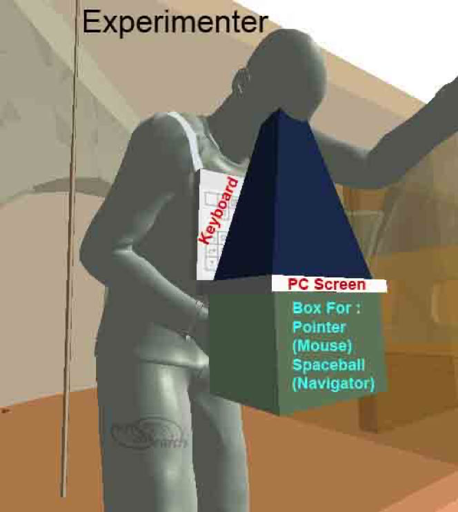
Next picture below depicts experimenter at work with a Cadmera calibration reference triangle on the floor. It is a simple frame with colored LED lights. A camera is also fixed at it's center (Corresponding to a CAD reference model). Calibration can be achieved simply by flying around in a computer model (with the perspective set to match that of the camera), until the CAD reference triangle does match the real reference-triangle on the floor. (These view matches between real and CAD are saved for continuing work).
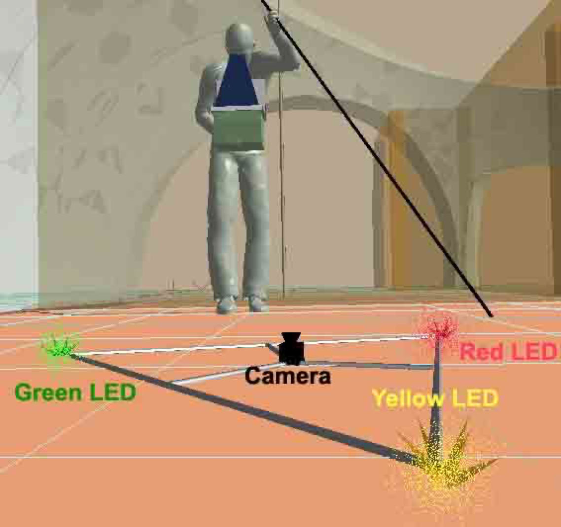
The modeling should be done first, with a good 3D setup. In fact it is actually advantageous to use good 3D software which supports use of the Spaceball, a 3DCAD-navigating device. My trusty software is formZ which supports 3D navigation along with multiple windows. I use an OS X system software called WindowShade to make formZ windows semi transparent. This is the element of Camera Lucida, here made digital. One can now see a reference drawing or 3D model, superimposed upon corresponding, multiple views of a work space. As real concrete is added, it can even be placed according to the model, without using paper plans and measuring tapes. (An interesting method for building with concrete and Cadmera methods is on this page, still due to be updated to include this model).
The next picture below Shows that the experimenter is checking the wall accuracy. In a real job, the builder could check placements live. In place where the brick or block is placed. (Pending better wearable equipment). The real-LED, mounted on a pole is now seen through the cameras and within the 3D-software. For clarity, one can use a flashing LED, the smaller the better.
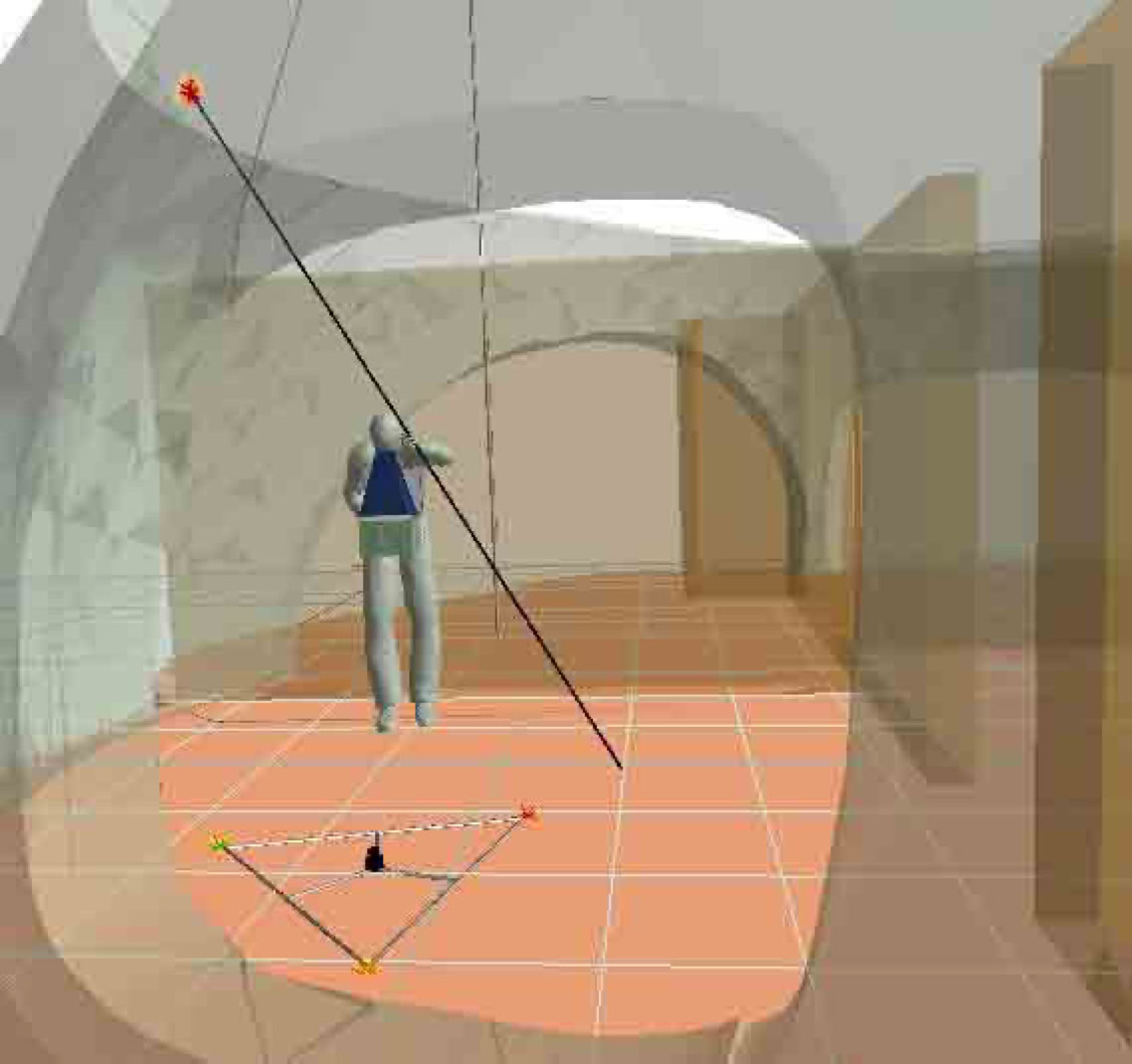
A great feature in formZ 3D modeling software is the ability to save unlimited views and to work with a graphical representation of the views. FormZ also has a window tool to assist matching perspective views. It's camera position can be manipulated as a CAD object or ultimately assigned to live cameras and otherwise retain perspective angle while navigating fly-through views. However, these inventive Cadmera techniques are not familiar to most CAD users or even formZ tech support. Still a further possibility is to use new features in formZ 6.x which allow live video to become projected on objects within the formZ model. This might allow a persons real workspace to be projected into the CAD model live. In other words the real-world video would be a back drop in the model so a builder could see real world progress inside the virtual model. Verify that what is built in the real world, in fact matches the model.
(Earlier Cadmera research follows below).
One camera and a semi-transparent lap top screen gives two views for centering machines like drills and punches. A semi-transparent screen displays the camera view superimposed over real view of. Combining both views together greatly improves aligning or centering. This is not possible with one view alone.
Placement of multiple cameras in a grid could potentially create views without perspective. Views without perspectives are essentially those used in traditional building. Having live-updated views of physical work allows the computer to be the final judge of all physical measurements. Today's computer gear already achieves this, although it is not widely appreciated. It is readily adaptable to all building but does need careful implementations.
Three adequately placed cameras alone is sufficient to computerize models . Perhaps even one camera could be moved around many viewpoints, with images saved for a multi-view compilation. A perspective-free image could then be processed and used in CAD work.
__
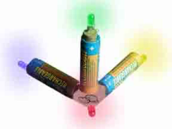
The cadmera concept came to me in 2003, with a space reference of three batteries and four LEDs.
First conceptual webpage was started in 2004 with a 3d point referencing tool to orient the CAD:
Digitizer Aided Building
Raster Aided Vectors!
Camera Lucida
Input-Output Digitizing / Computer Aided Craftsman / Computer Aided Labor
Live, real world measuring and layout is possible through CAD processing. Experimentation presently requires CAD skills. Nevertheless automated systems could vastly upgrade unskilled laborers. Otherwise CAD is by far outpacing physical building plan execution. CAD (computer aided design) could improve almost any layout or measuring work in real world construction. The needed ingredients already exist but are blocked by specialization. Specialization limits valuable potentials. Key service sectors are lost to CAD marketers. There is also a significant loss of brick and mortar productivity.
Art Or Science?
The apprentice, laborer, and craftsman all could significantly boost production with CAD used directly in live measuring and pattern work. CAD could close the gap of uncertainty between specification and physical execution of customized work. CAD could even measure "on the fly" in order to replace the measuring tape . Traditional measuring and layout tools slow down and complicate customized labor. Specialized laboring is typically enough of a feat of physical exertion, of poise and of execution. A large sector of the productive population possesses untapped spacial-geometric ability. These qualities combined, offer a marketable dream to computer developers.
Multi-cycle Photographic Interaction With CAD
A tool set is emerging , (needing little user training), which can measure and gauge movement of a marker between successive photos. Electronically linking the mark in the real world with the CAD plan improves accuracy. The same mark can be the cutting position of a real world tool or a gauge for positioning work materials, even bricks and mortar.
Photographic interaction with 3D CAD has not yet been promoted for common labor. Craftsmen and laborers are independently beginning to learn about computers as work tools. From layout of cutting patterns to framing structures, CAD can readily adapt directly through photos or video. The scope of CAD applicability is already so wide as to have blinded earlier recognition of these potentials. Relatively little further development could greatly improve computer aided construction, (a market windfall on all sides).
Software Examples
Perhaps most suitable are fire wire and USB cameras. Live video of work scenes can be delivered to a computer window. An example of software which can display multiple live windows of a work scene is SecuritySpy. It is presently promoted as a security software, however it will accurately display multiple windows. For example: four windows can provide critical 3D orientation information. The CAD model likewise can be displayed in four matching windows on top. CAD , for example formZ, can display four windows. All of which can be verified against the physical markers and materials of the laborer or craftsman. The formZ window can be made partially transparent to allow this viewing of two softwares simultaneously. The real work world and the CAD model are aligned, one step closer to using CAD as a real world measuring tool and as a building plan, all combined.
More Essential Methods
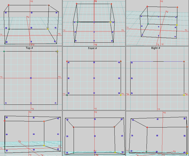
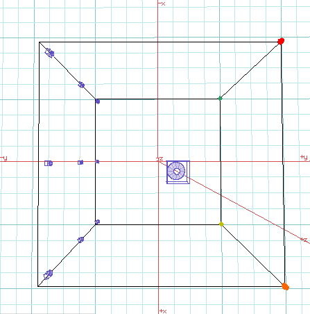
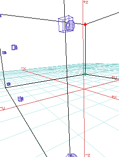
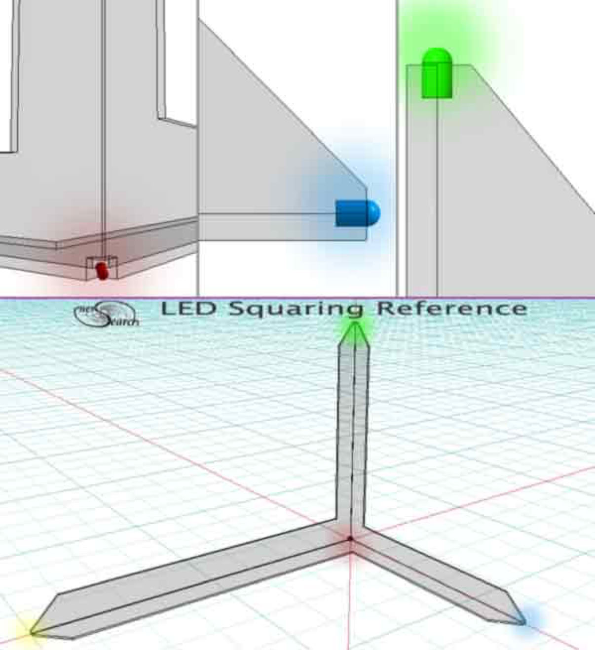
A number of work site viewpoints orient a CAD model. Digital camera images can feed a CAD program accordingly. Systems could vary according to scope, but enough overlap exists for common tool components. Cameras can be mobile with widely moving tasks or can remain fixed in particular positions. External triangulation of real, live viewpoints and markers can match CAD coordinates for real time patterning and fitting of work. Distortion of specified lens is matched through CAD perspective views. Key to this proposal, tiny, bright LED marker lamps are placed in the work scene. (LED means light emitting diode). Key work-scene points are matched to CAD coordinates. Cameras and/ or LEDs may mount on particular tools, may attach to workman garb or to building materials. LED markers also hold CAD orientation as camera views are switched respective to real world work in progress. Lights nearly the size of a pencil mark or larger lights may be packaged singly or multiply. A squared "LED space" example is visualized below, potentially useful for checking camera readings
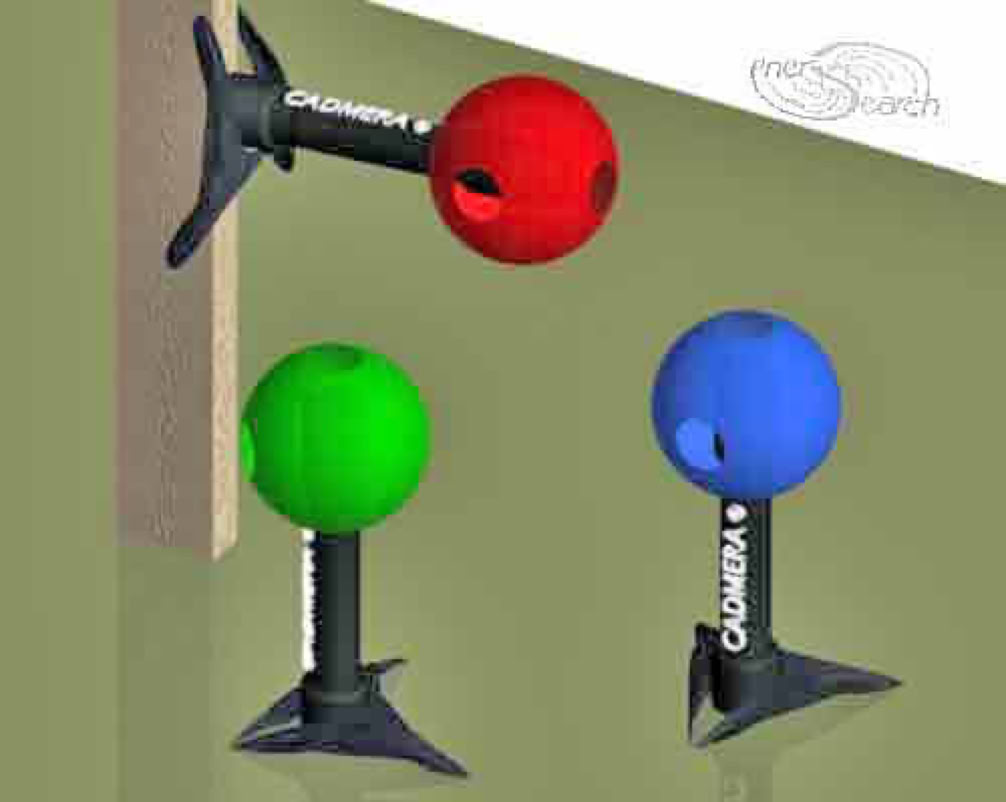
Proposed Goal: The interminable measuring tape could be replaced with two or more LEDs mounted on a square, gauge, push pin, magnet, or hook, ect... Bubble levels, plumb bobs and transits could essentially be replaced. Human fumbling errors are removed. Mental focus is enhanced. Even active tools like a landscaping rake or concrete screed could usefully incorporate cheap LEDs . CAD could track live tools to inform user of physical work (progress) status. Spherical camera housing in signature colors could help other cameras pin point each other camera-eye-point location. A wide range of trades could adapt to one common product base. CAD-camera: "CADmera"
Additional Experimental Implementation
Following are further examples, emulating said method with a readily available 3D CAD software. To test these concepts today, an experimenter can down load a formZ demo version and test many of these concepts. It matters not if 3D software is not advertised for these uses. Other softwares can be web searched and many offer trial demo versions.
The perspective view angle of a digital camera can be matched in the CAD window. Perspective views may prove satisfactory for some kinds of construction. A variety of concepts to improve this approach follow.
In formZ, the interactive shader called "Open GL" displays digital camera pictures very well. Thus real time work can display as an "updated slide show" behind CAD models which are also true to the camera perspective. Although formZ is not streamlined for automatically changing images, (updating real world views), such wizardry may become demanded through pluggins.
The "live camera image" is color mapped to a nominally rectangular CAD object, (equal to camera's pixel aspect ratio). As many "snapshots/ slides" as might be desired are storable, as normal images. Each such "snapshot/ slide" may or may not be useful for work history or for repeated tasking. Continuous image updating with consequent deletion of prior image is more appropriate for other circumstances.
Each view is displayed within a CAD window frame. formZ can display many windows simultaneously. Four windows has been found very helpful for general 3D modeling clarity. Experimenting with diverse uses could seem daunting, but efficiencies are recognizable with ample consideration. The interface of formZ is already highly customizable through user preferences. Diverse work environments are easily matched through customizing formZ interface. Furthermore, keyboard shortcuts can be personalized for many commands. Customized uses can be independently saved and latter re-invoked to demonstrate diverse customizations.
Narrower perspective view angles provide less linear distortion. Telephoto lenses provide narrower perspectives. It is usually not possible to use telephoto lenses due to the required distance needed to get the full work space in view. Therefore another system that may be employed is the "telescopic array". Ordinary perspective lenses may be grouped together in an array. A "top" (or birds eye view) of a construction site could be obtained by wide to medium angle cameras mounted on top of poles looking down. The resulting perspective views may then be both stitched and morphed together to reconstitute a narrower view angle. Ideally this approach could work towards an orthographic or axonometric view angle.
Even without these advances multiple views can be used manually today, in an exploration of tomorrow's tools. Practical implementation is available at several levels. Lower costing experimentation might use an computer with cable connections to cameras. (Alternatively, manually transported memory cards could update the CAD views.)
Dream-Tool Packages
Advancing innovation can use wireless technology for connections. A lap top computer which could attach to a workman's belt introduces portable usage. A stationary LCD projector could project work patterns to the material for cutting or fastening without the use of traditional markings, tracings and the like.
Reaching higher up the wish list, VR (virtual reality) goggles could replace both screen displays and projectors. Seamless CAD updating in a project is feasible without user updating of views. The LEDs used as markers could be signature identified by the software or hardware. Color/ frequency coded LEDs and patterned strobe coding could allow many tracking points to be addressed and a complex structure to be completely and technically tracked from CAD to finish.
An important milestone is addressing a CAD system through physical, customized work itself and not exclusively as a virtual model. Semi-see-through goggles should allow matching human vision with virtual CAD windows. Tasks like cutting patterns with powered hand tools could display the pattern directly through the goggles, given automated updating. Confusion of task assignments to laborers is completely removable. Both an employee or an independent worker can operate with greater confidence.
Highly portable computer equipment to mount on workers and camera devices to mount on goggle/ helmet rigging is practical. An experimenter would need to customize and adapt commercial products, but this is available to experiment with today. Virtual reality developers sell a variety of equipment which is experimentally adaptable for craftsman, foreman, artist or handyman. These examples should confirm that relatively little development will go a long way.
Triggering
The visual indicator called "snap"(virtual, targeted touching), has long been in CAD. Real world "snapping" is feasible for CAD in various ways. Since LEDs shine "monochromatic light", (one narrow band of color), there is a natural possibility of 3D CAD snapping to those narrow bands of lights. This and other devices promise to orient 3D CAD with real world work.
Another device for "hand free" operation and for keeping eyes on real world work is audio output. One example is sometimes used for "computer aided inspection" (CAI). A $10000 digitizer arm sounds off increasingly louder as a user moves it's pointer close to objects of a linked 3D model. This is an admirable feature for complex shaping and positioning according to engineering plans. Digitizer arms however restrict reach to the digital arm's length.
By contrast, camera interfaced CAD, has a much longer reach potential. Also, handyman and laborer tasks are satisfied with far less accuracy, than with hi tech engineers. So cruder, cheaper implementation eases product development. In the meantime while experimenters wait for developers to follow, there are some small tricks.
Instant low cost improvisation enables a crude "audible snap". A simple, adaptable photo sensitive alarm could be "taped on to" display screen, (perhaps in a corner). The sensor would be closely focused on the "zero" of the active 3D CAD plane. When the 3D CAD cursor snaps "off" of CAD plane and on to a CAD surface snap, the said "zero" display would change to the numeral values of the snap. This display change could trigger a photo sensitive alarm, (or tone), to indicate continuity. Incidentally, SecuritySpy software already offers motion detection digitally.
Final Notes
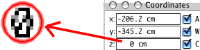
formZ coordinates -
Additionally, the author has noticed older video cards in combination with earlier versions of formZ (mid 1990's) also produced a hum sound with snap tools, which suggests a triggering source from audio sound. It would seem easy enough for software developers to add useful trigger outputs from CAD.
While computer aided machinery, (CAM) already serves manufacturing. The systems described here deals with a much wider variety of possible tasks. Potential tasks are too varied, too far and too few between for CAM to address. The physical size and investment required for CAD-CAM machines to address many laborer intensive jobs is obviously prohibitive. Arming the laborer force and power-equipment with CAD tools is possibly more innovative and artful than inefficient excesses. An interesting possibility is that the aggregate product should produce greater value than a machine cost, which was used to produce it.
Who would understand this particular niche of CAD potential? Those who have struggled between measuring tapes and CAD ! May those who agree please step onward and succeed.
Sept 13,2025: Google's AI, or any chat may agree and recommend with the equipment concepts: Inputs reflecting the above key points adding the terms "converged lidar/lasers to define cut and fill in land shaping or diverse structuring applications. Integrate computer aided coordinate functions in real life…. “Consider use of converged light patches from two lasers, for the sculptor to find and establish fill points according to CAD modeled landscaping.