The following content was first posted in 2009 describing... a well-formed formula-based helix which actually generates a tetrahedron structure. My professional modeling software consistently generates this geometry and therefore this seems significant.
These tetrahedral paths are apparently a form of the helix. A helix and a tetrahedron, both, apparently! A nine segment (faceted) helix formed along an equilateral triangular path can actually actually form a tetrahedron. Wire frame model below shows the helix-segment directions. This helix radius example is close to 10 times larger than the triangular-path, (along which, said helix does form).
The "show-direction" render immediately looked like an interesting coil for new, tetrahedral EMF effects! As the ratio of radii is increased, the alignments of the helix segments more closely align with a superimposed, precise tetrahedron. There are many interesting aspects of this geometry.
The first two examples were generated using a 10:1 ratio. (The ratio is helix-radius to path-radius). A green-equilateral-tetrahedron is compared with a blue tetrahedral helix in the picture below.
The helix radius in this example immediately above, is many times larger than the triangular source path radius. (Ratio differences at work). These are screen capture images from 2009, (using formZ):
The red tetrahedral object (immediately above) is the "Wire Helix Along Path". The small black object (visible at higher image resolution, would be the flat triangular path. Downsizing image for bandwidth conservation lost the black colored pixels).
So next is a model with a larger, red colored source-path triangle. (Barely visible even the low resolution image).The resulting, facetted, 9 Step helix, (3 'turns' per cycle), was then Swept or made into a solid to emphasize the approximation-feature, of true equilateral tetrahedron rendition.
The fact that an absolutely ea qua lateral tetrahedron is not made by this verifiable procedure, actually may yet prove useful. It may render advantages in case the helix path could become a solid wire. (My own interest in this particular regard is drawn to using bi- filar wire segments of each tetrahedron leg-- In order to project and arrange electromagnetic fields. The "slightly mismatched" vertices can represent the width of bifilar arrangements, as these would 'angle' at the vertices. Also, the slightly shorter stature of this primal tetrahedron may be discovered to provide other significant features of field projections. (However, a comprehensive investigation has not been made, regarding just how closely, a helix can be adjusted, to match equilateral tetrahedrons.)
At ratios greater than 100:1, equilateral tetrahedrons are closely approximated. I also wonder if there might be variations of math formulae for helices, wherein a more equilateral tetrahedron will generate. The image directly below reveals a consistent limitation for the trihedral helix. Regardless of very large ratios, there always appears to remain gaps at the vertices. Gaps which equal the triangular path segments (or sides). As in "Top#4" view below.
The facetted helix in the image below has a relatively low ratio. As a result, the helix facets or segments do space further apart. Observing the results of differing ratios helps visualize the geometry of this primordial tetrahedron. So the following helix can visually suggest a geometries to electrify:
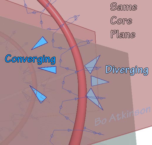
My own interests span various fields of endeavor, only partly technical in nature. The blue framework above explores the possibility of forming wires, to produce a specialized magnetic field: One poles is split into three poles. The remaining pole is opposed to these. Yet exhaustive trials deserve testing modified circuits. By changing leg connections and hence the field directions. The blue framework can represent the spacial relationships of wires, (or helix-coil-turns). Visualizing the tetrahedral star circuitry visualization below was added to this page on Nov 2012.
Next is a view at a slightly different view angle. Notice also that the spacing of the wire frame models vary. Each model is utilizing a different ratio between the source path, equilateral triangle and primal helices. (These may yet be adapted to more intricate frameworks like my Fractal StarTetrahedron. Visualizations of the expected trefoil, Split pole, field effect, will be added in future.
Yet another model below visualizes a quick render emulating copper bars with sharp corners. To emphasize the physical challenge of forming and 'perfecting' a copper, tetrahedron circuit: The close bars/wires would be insulated but touching. If not to use square-cross sectional conductors. (Yet another experimental issue to study.).
Next model below explores a flat faced tetrahelidron, for research with wave guide effects. The plate separation is exaggerated to represent insulation which allows this configuration to form a series electrical path around all plates. (through centralized interconnection).
Next below is another pending example for proposed research. On right below is a tetrahedral arrangement of 'coils' and to the left is the 'disassembled' or spaced out assembly. To emphasize the the geometry of the arrangement of 4. conical coils.
My expectation is that the above configurations would provide more interesting field interactions.
Update of 2021 was finally uploaded here.
I would closely observe and adjust the resultant field concentrations towards the tetrahedral center. At the most central point, the three uppermost coil fields could 'funnel into the bottom most coil field. This construct could be studied alone or as one intact component within larger configurations shown below.
By contrast a single, tetrahedral coil, may have less interesting fields. Scanning tunneling microscopy images published in Science News Magazine, ("Super Conductivity: Two Teams, one view"April 6, 1991, pg 215) appeared very much like my image on the right, above. The concept of creating circuited coils at various prospective scales should be very interesting.
Above is one 4 coil module. My curiosity involves more elaborate configurations: Why not assemble quantities of these coils in more elaborate configurations? 2012 page on spiral orthogonality ~ 2012 page on 1980s coil work.
Next below are suggested assemblages for tetrahedron coil modules (pictured last ). Symmetrical arrays of tetrahedrons pictured where each drawn tetrahedron represents multiple coils or plates wired in series.
Further examples may be seen here. Electrical circuits for these would interconnect by mid points and by vertices, dependent upon the assembly... There also remains the fact, that 3 legs of the primal tetrahedron (heli-tet?), have wires with opposite alignments (or polarities). While the remaining 3 legs are single wires. I will elaborate on my work with these assemblies as more observations are collected from from experiments. I would have enjoyed experimenting with coils and better equipment. My experimental coils were much cruder in every respect.
An application of this model intended to fit the The Energy Wave Theory, (EWT), was attempted and was unsuccessful.
A year later in 2021, this same model was revised and posted in a new webpage.
The following models renewed my modeling efforts before discovering EWT moths later. A mathematical helix formula generates three surprisingly aligned surfaces resembling a tetrahedron. It's base is open and all of the triangular apex heights are equal, unlike the regular tetrahedron apex-height, which is greater than it's other attached triangular heights. The parallel edges which are finely separated, provide infinitesimal cracks at each of the three, vertical or pyramidal edges. The length of base edges is shorter than the vertical edges, which differs it from the tetrahedron, which has all equal edge lengths
A more acceptable name might be Helical Trihedron, to replace the earlier suggested name of Primordial Tetrahedron, where the earlier question of antecedence is still open to discussion, in the fundamentals of geometry.
Discovery of this particular trihedron:
In February 2007 I tested helical structures wound around basic geometries including the equilateral triangle and eventually discovered the striking resemblance to the tetrahedron, as described above. The convergence of two dimensional (triangles) and three dimensional structure (polyhedron) was questioned, as a hypothetical explanation, (hence the previous suggested name Primordial). The three apexes increasingly converging with the increased ratio of helix diameter to the helix path, (and structured with straight segments instead of curves), has peaked my curiosity about the classification of dimensionality, (and to be continued on another page).
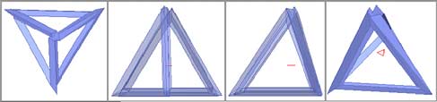
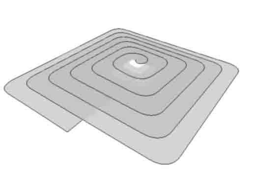
Next images below were earlier efforts to convey what it means to form or wrap a spiral around a triangular path. A smaller scale helix is used and the helix itself is shown with a variable number of turns and variable segmentation. 
Earlier work first began in 2007. For years i was perplexed as to how to present the relevance of this geometric discovery of a particular relationship between the helix, the solid tetrahedron and a simple, flat triangle. It almost seemed some sort of greater discovery associated with it might transpire. Making a living diverted attention away my favorite studies which relate to geometric patterns and applications. The next image views the same helix object with variations of steps-per-cycle, (from differing view angles) and includes a solid tetrahedron for comparison, (in green). The image includes variations of helical frequency and smoothness, wound around a triangle. ~ TetraHelidron?
I additionally wonder if this model might relate to toroidal geometry. In that by adjusting the ratio of diameters, (path diameter to helix diameter), tours-related objects are generated. Morphing relationally, also can manifest self-interfering tori. I further visualize relationships of rings, tori and helices. This link will show an experimental concrete rendition.
This additional link discusses many of my structural uses of rings.
Free Exchange of Ideas (Portfolio which includes captions).
I actually have shared many of my geometric models for free but also welcome highly customized work.
Hire Bo for low cost geometric modeling.
Bo's Pictorial Portfolio -- index.html
Envisaging Transverse Force Fields: Laminated, parallel coils are considered on this linked page.
~~~~~~~~~~~~
Discussion about my website content is welcome.
![]()
Note: My 100s of pages on this website, http://harmoniouspalette.com, are placed in the The content on this website, http://harmoniouspalette.com, is placed in the public domain only as a free exchange of ideas and as a "hard studied wish to serve life". The author assumes no responsibility for the improper use of the concepts in these web pages. All relevant laws of life and local codes should be verified and observed before any building or experimentation proceeds. discussion is welcome, please write. Bo Atkinson and are furnished "as is" and "open source". My work is posted as a free exchange of ideas and as my "service to others". Caution: The author assumes no responsibility for the improper use or improper misuse of the concepts in these web pages. All relevant laws of all kinds and local codes should be verified and observed before any building or experimentation proceeds. Bo Atkinson