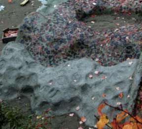
Cement wall sections are sand molded and reinforced with wire rings.
(Pictures intentionally degraded for quick www downloading)
This page reports experimental progress and observations of ring reinforced cement. The contoured styling added some framing or ribbing effect. Of special interest was exploring a ringed, tessellation, framework concept.
Following are a sequence of pictures which record the progress of constructing a wall section.
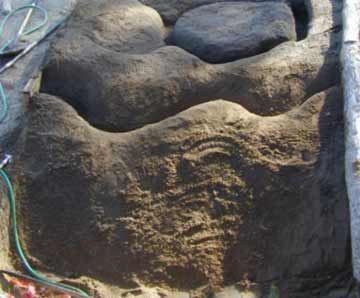
Picture#1 Sand mold is being smoothed. Rough sculpting done with flat ended shovel and foot compressing, (stomping) sand. Smoothing is done by hand.
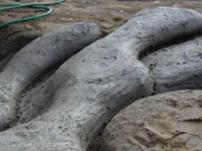
Picture #2 From another view angle, the sand molds have been coated with a slurry coat of cement and sand. The mix has been watered to a soupy consistency. Soon after placement of the soupy cement mix on the sand mold, the excess water bleeds into the sand. The wet cement is spread to finger thickness or less. Working it with gloved hands evens out the thickness and compacts the soon de-watered cement to a low slump, (desirable condition).The next step could have proceeded immediately if extra labor had been available.
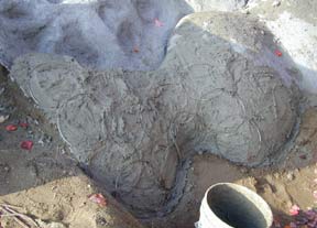
Picture 3 The first coat of cement has set and another coat of lower slump cement has been applied. Then wire rings are placed in tessellating fashion.
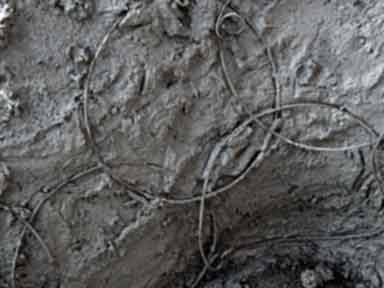
Picture #4 A close-up picture of preformed wire rings, slightly bent to conform to contours of mold. The wire ends were simply "barbed" and hooked to form rings before this step. A rough coat over the wires only imparts the "dimpled" effect seen below.
Picture #5 The rings have been placed in all wall sections and a third, pigmented coat of cement is being textured with autumn leaves. The ring framework is now visible on the surface.

Picture #6 After the cement has cured, a small home made back hoe lifts the wall structure away from the sand mold.
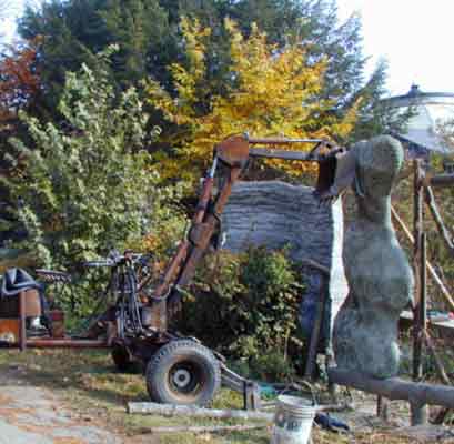
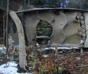
Picture #7 Finally the wall section is placed on a ferrocement "foundation". It is being built on top of a peculiar, undulating, swerving ferrocement foundation. The foundation is rail like with piers sunken nearly 3.5 ft or a meter into the ground to protect against frost heaving. The "rail" was positioned well above ground to avoid contact with the rising ground of frost heaving.

Picture #8 Progress was slowed due to cold. To the left of the two sand molded wall sections is a continuation of the wall. This other wall section was built using flat spiraled ringforcement .
Click here for a report on the other section of connected wall using the flat spiraled form of ringforcement.
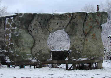
Picture 9# Finally all contoured sections of the wall are in placed. The short space between both mentioned sections of wall is filled with still another ringforcement concept.
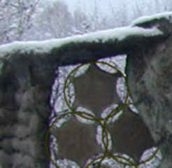
Picture 10# A corner of picture #9 has been enlarged to show the "ringed tile". This picture has been penciled over to emphasize that each individual ring has a cement tile inserted integrally. The ringed tile was originally conceived somewhat as a masonry unit where the open spaces around the tiles would be mortared in. These six pointed tiles are an optional shape. Other shapes are contemplated. The artistic style of rings without mortar will also be explored.
Picture #11 Here is the back side of the contoured wall section. The edges of each contoured section are curled towards camera. This additionally provide framework to the structures. A ferrocement buttress shaped like a quarter ring connects to wall and to a backbone shelf which stiffens the top of wall. The rough texture is due to sand casting, (top of page).
How long did it take?
This building experiment (mixing and placement), was carried out with one worker, (Bo himself). Time was approximately spent as follows. One day for the sand molds as pictured above. A few hours for the slurry coat. A long day for placing rings in a rough coat of medium low slump cement, (along with lifting anchors and ties). A long day for coating the rough surface with pigmented cement and pressing autumn leaves down on surface. A couple of days for experimentation with ring making tools and for ring production, (this after years of thinking about and tinkering with rings). A day for rigging each wall section and placing it on foundation. Also, a day was spent building the temporary scaffold to receive wall pieces. Other unreported time was lost and not counted. The project is still underway at this writing, delayed by weather. Computer and imaging time is also not counted, but many more hi res images are saved for a possible CD or www animation of this project. (Images on these pages have been intentionally blurred to travel quickly over the www).
Preliminary Conclusions
Ringed tessellations adapt well to contoured surfaces which do not accommodate flat mesh reinforcements.
Tensile strength can easily be incorporated in ferrocement (or thin concrete) without dependence on welding or fasteners.
Overlapping reinforcement rings interlock the overall tensile strength through the intervening overlaps of compressive media, (In this experiment, concrete).
Production of other composite materials could benefit from ring reinforcement.
Theory
While the diameter of the rings used here varied from10X to 20X the wall thickness, the ring diameters could practically vary from micro to macro and the materials also could vary from cement to any composite. Ringed particles or ringed parts "flow" together with less resistance to placement, thus easing any construction or manufacturing process. The present limitation is simply the lacking availability of mass produced ring products and a lack of technological priorities for improving (mass) ring production.