Experiment With Multi orbital Coil Structure
I have always been interested in geometrical structure, coil induction and harmonic resonance. Finally in the last month of 2012 i decided to mock up an experiment- project which is generally summarized in this animation:
Pictures of the Winterbourne Stoke crop circle reminded me of my long interest in reflexive coil windings. I have described more of the underlying concepts here. It was just a shared idea until a web friend suggested 'crowdfunding'. I had to refresh my understanding of this sort of funding, (from a self employed perspective). This sort of promotional effort would take up valuable time, possibly without any crowd, (ha, ha, crowd satisfaction). However this suggestion did provide a spur to detail more 3D modeling and it jump started construction. I love geometric visualization and share this on the internet.
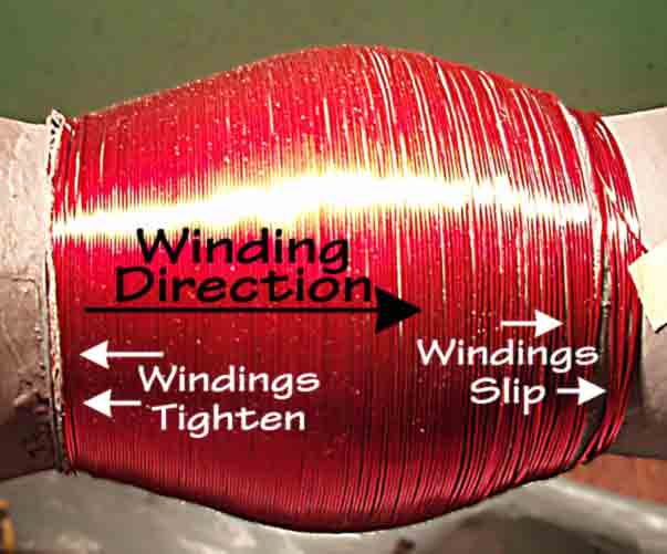
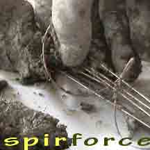
The cross sectional components interpret a resemblance to the crop circle. At least this did come-up, inside my imagination. The reflexed-radial-path is connected with and contrasts with the spherical-orbital paths. Finally in February 2013 i wound a version and energized it with feeble currents. In the image below, an outer layer winds as a spheroid. The inner winding radial winding is pictured further below.
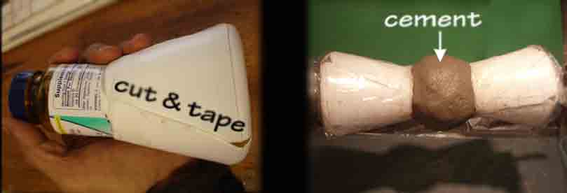
The layering of the pictured coil winds over a cement core. The ends of the core are old plastic jars, cut and taped. Multiple alternating layers of wire and ferrite (magnetic) coatings were lamented in place. The next picture shows the internal core before any layers were wound or coated.
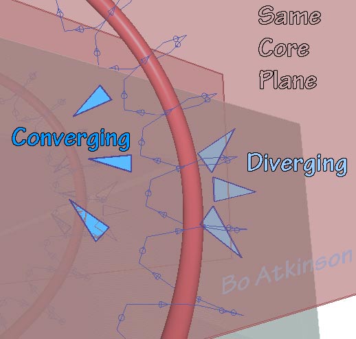
The inner radial path was made differently than the schematically modeled version in pictured below. Ordinary wires naturally would tend to over populate inward-radial paths. Or, radial wires will under populate outwardly. The transverse winding relationship was the intent of this exploratory design. To exchange the traditional paths of the transverse electro-magnetic wave. The reversal of dielectrics and magnetics was explored in 3D geometry software, (in the next image below).
Note the nearly orthogonal or transverse, (or 90º) relationship between radial and orbital paths in image above. There happen to be a variety of practical solutions, for winding these. I will include yet another way to transect laminated fields. By conceptually morphing the two paths with a 45º version as modeled next below. To compare 90º alignments with 45º alignments. To shift the major axial alignment 45º with respect to all windings, (wires or paths). Dual sets consisting of one red and one green "winding" are laminated spherically, (except that many windings are omitted from illustration to better see the interrelationship of windings). I say laminated to imply concentric, or "onion-like" layers of paths, (or of windings).
The Interactive laminations connect in series or in parallel. A nominal series, or serial version is illustrated above. Meaning that each laminar layer is end connected, from innermost to outermost. By contrast, a parallel example would omit the black splines in the geometry portrayed, (in the image above). Omit the back splines and connect all path sets in parallel, instead. The objective is to compare the effects of transverse geometries. Next is an image of the same model above, with all but one serial connection shown:
Instead of radial vectors used in the first geometry models presented above, i decided to try using an un-insulated coil wire. This naturally allows the current to flow across the coil windings. (In case consistent contact is made but i expect my connections varied in connectivity). I didn't expect a perfected solution here. I am just studying the builder-potentials for now. Modeling with geometry software and then modeling with physical models , along with preliminary testing, all spurs on further, creative solutions.
I did some initial resonance testing. My feeble currents were not expected to promise much. However, i was looking for the harmonic resonances which i sometimes noted in the past. (I haven't done this type of testing since the early 1990s but am trying to reestablish my earlier harmonic responses). Only some phase shifting was noted on my first tries, here. My aged test equipment was used. If fate allows it, i will look for ways to improve this experimentation with more principles and practice. As the season is turning at this writing. It calls me away to other work commitments. (2018 Edit: I never did get back to this experimengtation and furthermore find myself less employed, as admittedly i always dreamed of a decentralized, free-from-the-matrix lifestyle).
This page has discussed spheroidal coil cores. Specially treated laminar or layered coils, in cylindrical or toroidal forms are also discussed. The quantity and interrelationships of orbital iterations can actually vary. I will try several variations. This sort of experimenting inevitably provides more visions of alternative geometric implementations.
A helical path winding around a sphere's-orbitlal paths (image example above), i will call "orbital iterations". There is an "odd and even", repeated succession of orbital alignments, which i will to elaborate more on-- This elaboration will be on my inductive coupling page. My expected method for constructing the spherical resonators will be something like laminating together an onion! (Imagine adding onion layers to visualize spherical lamination.) My further experiments will be hand molded with somewhat cementitious mixes. Except actual cement might not be needed. Various resinous admixes will be tried, with magnetic powder additives, (like ferrite powder). A spherical, radial-path-conductor , (the purple conductive path in the animation) , could be a conductive paint material. Specific material choices depends on the budget. In the build example above, the bare, uninsulated, conductive wire was used. I expect that potentials of two electrical directions, at roughly 90º respectively,, may give inconsistent results. Yet this sort of tinned winding might suggest a substrate to coat the surface with solder. This links to cementitious hand molded work, only to show some of my exploration of hand molding cementitious mixes.
Envisaging Transverse Force Fields: Laminated, parallel coils are considered on this linked page.
So why consider a crop circle for inspiration? I am somewhat an artgineer or one who dares to strongly integrate distinct disciplines. I have always taken inspiration from nature and all of it's constituents. Crop circles may have uncertain causes but the inspiration fits my interests. The popularity of crop circles also make it fun for me. Even though i may never visit a crop circle in person. So thanks to those who place crop circle pictures on the internet. I'm not sure of the date of this particular Winterbourne-Stoke crop circle, but i think it might have appeared in the mid 1990s. I first recall seeing this in July 2012 and have been wondering about the "reflexive iteration" (as it might compare with my spherical coil interests) . I edited the image to strongly emphasized the outline of interest.
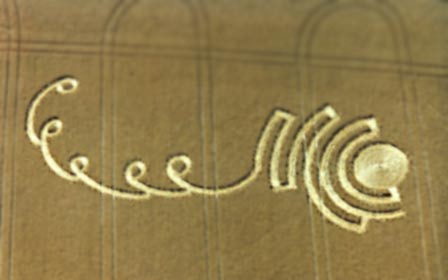
Winterbourne-Stoke-England Crop Circle
It was in 1994 that i began working with 3D software: Silver Screen on DOS followed by formZ on MacOS7, in1995). Both of these softwares allowed multi copies of a profile to be rotate-copied around an axis. If the outline in the image above is rotated as a profile, around a 3D axis, the result is almost similar to my proposed experiment. However my associated 3D models have taken many hours to develop, on my computer.
This link begins to describe my history. I will be adding old and new models to this page and more links-- As my life allows me to do so. In an exploration of geometry to represent electromagnetics.
My study of formal geometry is limited to use of modeling software and forum participation at http://www.formz.com, since 1995.
Following are my only formally recognized diplomas, with my formalized name:
I have been posting my work on the internet since the late 1990s. Just as soon as it was made public and assessable to my area of Maine. I have always shared my work as a a free exchange of ideas.
I welcome free exchanges of ideas in discussion.
Bo Atkinson
~~~~~~~~~~~~
![]()
Note: My 100s of pages on this website, http://harmoniouspalette.com, are placed in the The content on this website, http://harmoniouspalette.com, is placed in the public domain only as a free exchange of ideas and as a "hard studied wish to serve life". The author assumes no responsibility for the improper use of the concepts in these web pages. All relevant laws of life and local codes should be verified and observed before any building or experimentation proceeds. Dicussion is welcome, please write. Bo Atkinson and are furnished "as is" and "open source". My creativity is posted as a free exchange of ideas and as my "service to others". Caution: The author assumes no responsibility for the improper use or improper misuse of the concepts in these web pages. All relevant laws of life and local codes should be verified and observed before any building or experimentation proceeds. Donations to me would be welcome, for me to continue or to up step the progress of these works. Cooperation might be possible as well, please write. Bo Atkinson
~~~~~~~~~~~~