Transverse Coil Dynamics : Winding vs Interleaving
The typical field geometry and typical conductor geometry exchange geometric placements. The typical magnetic field will hereby become the electrical conduction path. While the typical electric field will hereby become magnetic field path. This effort can take many forms which are introduced on this web page. First the typical arrangements of electric and magnettic fields is given:
These pages are under reconstruction. A hollow core version of this concep, was added on Feb 2013..
This 3D CAD research dates back to 1994 when i purchased Silverscreen software, for DOS 5 operating system on a 486 computer. One of the first modeling tasks was to 'spin' or revolve wavy profiles around an axis. Silverscreen was able to spin wavy profiles around an access. It was able to rotate-copy many profiles and distribute them around an axis. But i could not make a surface much less a true 3D solid, with that software. In 1995 i found form, but that required me to buy a mac computer. It has taken years for today's solid modelling capabilities to develop. Silverscreen was primitive compared with today's CAD standards but it was the strongest-affordable software for solid modeling in those days.
Spiraling Sphere Models
"Spinductor"
A 1994 CAD Study By Bo Atkinson
Models on this page can be viewed as
flat spirals which are rotated on or near a polar axis to describe
skins. By adding thickness, usful experiments in physics will
go beyond ordinary electromagnetic induction.
This skin was made from the
basic flat spiral which
was then copied and rotated
10 degrees on (undrawn) axis
which passes through the
sharp connecting points.
The resulting pair of
spiral lines were then
"skinned".
The black and white wire frame graphic
above, is now rendered with
semi-transparent skin to
enhance visualization.
Here the skinned spire
is further
rotate- copied.
This is a partial,
"concentric, spiraling sphere".
On left is sort of an xray of the
full concentric, spiraling sphere.
A much narrower angle of
perspective was used than above
in the partial version.
Here a single section as in
the first graphic, has been
"unfolded". The long shapes are
flattened out to better show
their pattern.
Here is one half of the cross section. -->
Below is a bigger JPEG,
offering a clearer picture. A black line drawing similar to
the one on the right.has been superimposed to delineate
the cross section profile. Also
More on the history of this reflexive geometry is added here, (Feb 2013).
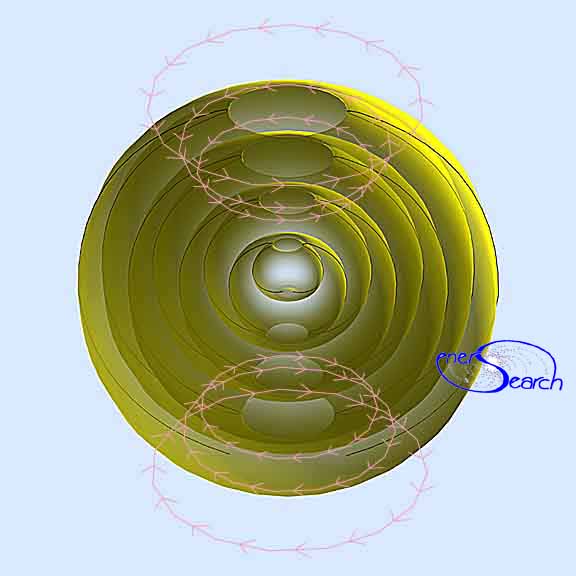
Below: The "spiraling
sphere" above has been adapted as as an electrical inductor,
hense "spinductor". The shell like structure above,
is used as an electrical conductor. Other adaptions are also under
consideration.
The "polar" openings at top and bottom of this graphic may be enlarged by
use of conical spirals in the 3D model. Conversely, the polar holes may be
essentially closed by use of a flat spiral in the 3D model. This concept
grew from my childhood speculation: If an electromagnet could be spun fast enough,
would i see light? (What children think of!).
As an alternative experiment, the electrical and magnetic fields may trade places.
In this new experiment, the red and blue symbols are regarded as electric current,
which travels in an electrical coil.(A graphic diagram will be placed here, when i
find time to do this).. The yellow arrowed path becomes the magnetic path,(during one
electrical pulsing of coil). I suggest the name "retroductor" for this
experiment, since the magnetic field is forced up and down longitudinally. Click here for more inductive concepts rendered via CAD (306 KB !)
During the 80's and 90's i made various efforts to build different inductor
experiments which utilize the electromagnetic fields mentioned here. (These
experiments continue, at some point i will post them in detail at this site).
If i had the chance i would like to adapt these geometries to plasma experiments
and also to discussions in cosmology. (Here is one example of one
attempt to apply bi-axial geometric concepts to cosmology).
Click here to see "hyper" spiraling, concentric spheres.
Tetrahelix As Prism, Light/ Ray Tracing Experiment
Tetrahedron used as a mold to model a "poloidal" biaxial structure.
Email comments

Note: My 100s of pages on this website, http://harmoniouspalette.com, are placed in the The content on this website, http://harmoniouspalette.com, is placed in the public domain only as a free exchange of ideas and as a "hard studied wish to serve life". The author assumes no responsibility for the improper use of the concepts in these web pages. All relevant laws of life and local codes should be verified and observed before any building or experimentation proceeds. discussion is welcome, please write. Bo Atkinson and are furnished "as is" and "open source". My creativity is posted as a free exchange of ideas and as my "service to others". Caution: The author assumes no responsibility for the improper use or improper misuse of the concepts in these web pages. All relevant laws of all kinds and local codes should be verified and observed before any building or experimentation proceeds.
index.html