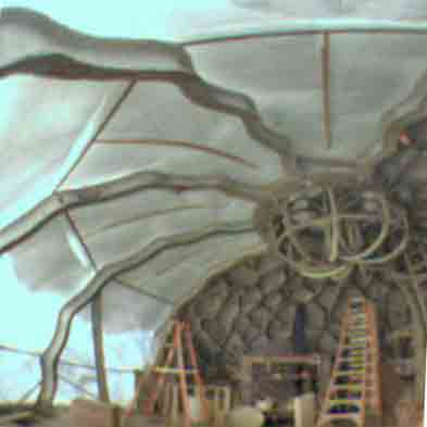
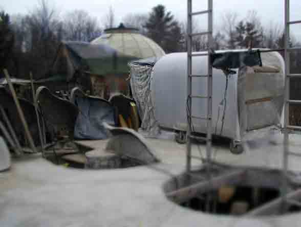
Thin shell ferrocement reduces labor investments and also can reduce a taxable-structure-perimeter. Common cement performs well in a thin shell for harsh and temperate climates. First picture: 2008 additions- Glazing the wavy arches and additionally, a donut truss spans the oculus (on top). Winter snow covers the upper glazing. Glazing material is "corrugated" PE. This entire "research project" is a one man effort, from design conception to muddy labor, (with very-occasional helpers).
Picture Below: 2006: Inner tube forms "float" overhead, forming cantilevering coffers !
Coffers provide 3D structural reinforcement, much as a bee hive is strengthened by the cell walls.
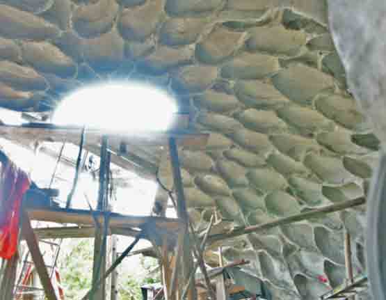
Photo Below: Mid-July, 2006 Innertube Form work for the ferrocement "leaf" panels.
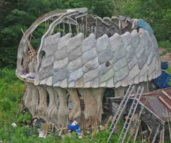
Circular tree groves inspired the overall building concept.
2004 Pictures, forming and raising the wavy arches-
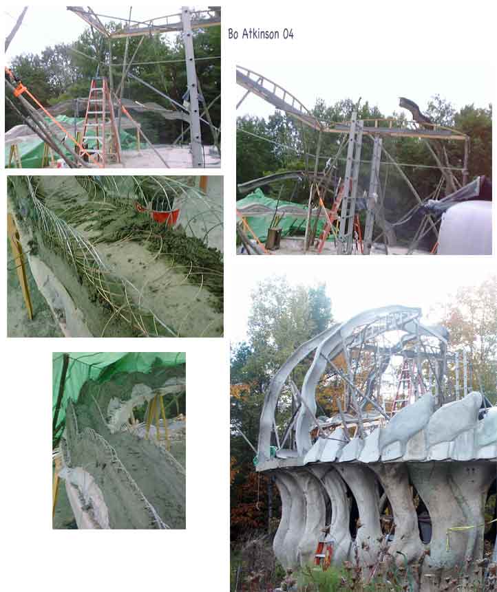
Above-- Forming of curved and tapered I-beams made entirely of rings and cement. Below, trial and error search for new panel building techniques. Plenty of difficulty due mostly to primitive tools, (which consumes time). For example, a machine to feed flat wire spirals could save time or a machine to weave wire could speed up work and compete with other building methods. This particular structure uses minimal material amounts while extra labor has compensated for lack of better tools. The search for invention is expensive, not the structure itself.
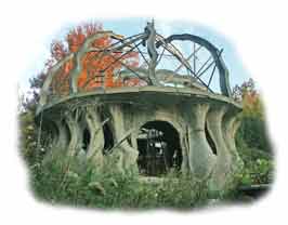
A reinforcement principle is also explored. It almost follows the example of chain mail. Chain mail continually readjusts to curvature while maintaining surface reinforcement. By comparison, ring reinforcement or "ringforcement" also adjusts to curvature, for the building process.Once the form is found, it is locked with cement permanently. Ringforcement rings are interlinked by cement filling alone instead of inter-lacing chain rings. The antique chain mail functionality is traded on for solid building compound curves. 2008: Glazing & Donut Truss Experimentation

Wet-tilted cement panels are building components like bricks and mortar. Wire and cement are here used instead. Improved mesh handling widely expands the design performance possibilities. "Mesh" is fabricated in situ with cement installation. Use of weld free wires might improve building process efficiency. Weld free wire could reduce labor and energy needed while at the same time reduce losses of ultimate tensile properties, (where mesh welding reduces ultimate cross section of welded wires). Thin structures conserve both energy of production and space. This page has been progressively updated since the project beginning in the year 2000. Though intervals of actual work were sparse over these years. Research explores both single handed prototyping and highly mechanized system possibilities. Older project descriptions continue below.
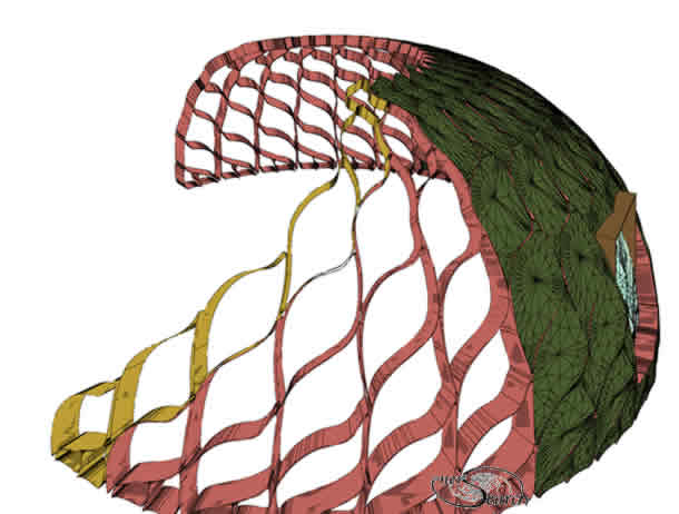
Three functions are combined into each panel:-
shingle, shell and frame.
![]()
The example suggests a repetitive canopy of leaves. The leaf edges provide natural framework outlines. Other patterns could likewise be "engraved" for a framework pattern. The illustration above shows leaf edges rounded. A cut-away schematic below shows exaggerated frames in pink and yellow, with shingle portion in green.
Traditionally, framework is usually built first and later skinned over. What
differs in this approach will be-- Apply the cement to shingle mold nearly
tilted horizontally together with frame work,
(simultaneously on the same mold ). Then tilt this wet cement panel, directly
into final position.
Model
below
distinguishes the frame and shingle, but in real life these components were
actually connected through sculpturally rounded "gussets".
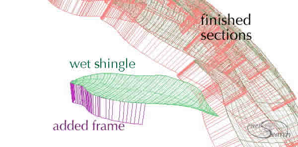
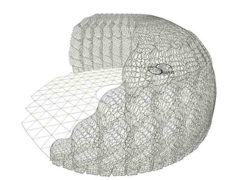
Illustration below attempts to show preferred roundness of frame and shingle connection. Overlapping rings are displayed to give a sense of reinforcement scheme.
Update of 4/10/03. Much less was finished on this project than hoped for during2003. A single handed effort was made to 1] improve application of stiff, small gauge wire for reinforcement, 2] devise tilting molds 3] proceed with construction. Besides these tasks, summer time income jobs took up most of summer of '03. Inserted below are pictures of the first wet- tilt leaf panel. This dome is a second floor, you may see the first floor here, (click on blue writing).
Above: Leaf panel mold is covered with fabric and placed on a tilting tilting base. First course of panels are already in place. Crude edges reflect the low cost, high tolerances in use. Edges of picture are faded to speed www download. Background is tree just turning to fall colors, the dome is floor above ground level. This proved too difficult to continue very quickly, but was opportunity to study wet tilting issues.
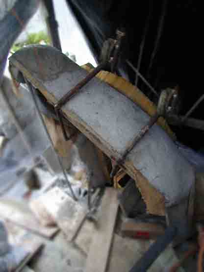
Photo, above: After placing cement with wire ring reinforcement, the leaf shaped panel has been tilted into final position. The frame for tilting was made adjustable for tilting at a broad range of heights. Old car jacks, scissor type, were welded together along with other adjustable features.
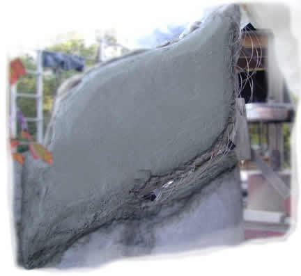
Photo above: View from outside shows the cement panel which was assembled inside dome to be, on the level for easier placement of cement. Now that it was tilted up, into final position, the lap is being cemented to finish a shingle style panel. Exposed rings are visible in photo, (bottom right). The steep angle was slippery enough to necessitate wire ties to mold, (temporarily).
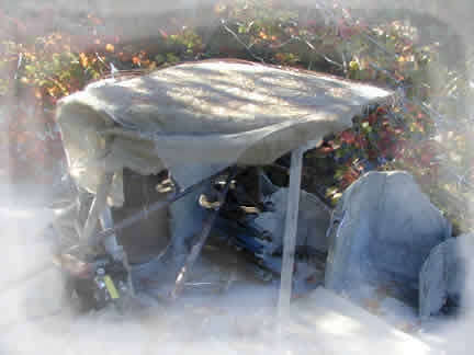
This cement work was been suspended until March 04. A small shelter on wheel was set up to allow winter work. A sufficient, movable winter seal should allow continuation for cement work. A quicker method to secure wet tilted cement was studied. A foam rubber cushion, (recycled mattress) was clamped over wet cement before tilting.
A low budget, sweat-equity approach allows one person to do all work in little steps each day. A"slow growth" and lower stress approach also permits a person hold another occupation while building a ferrocement structure part time -and- as a good physical exercise regime. More specialized equipment could speed the process. Larger crews, greater systemization and general optimizations could also speed up building.
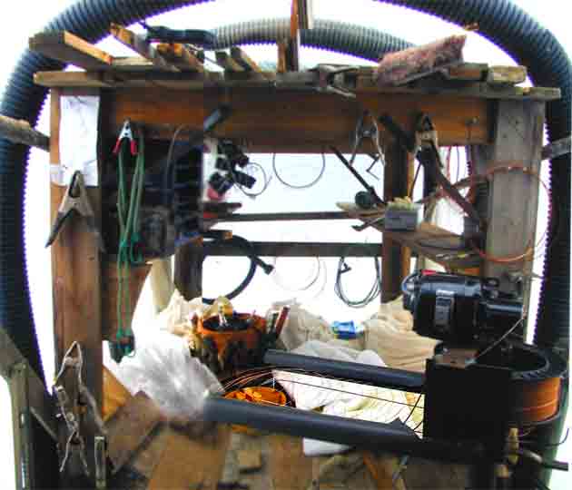
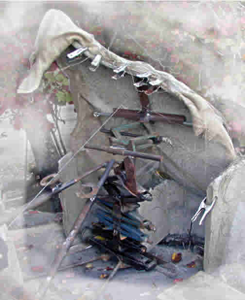
Above is the interior of the little shelter/ cart. The cover is corrugated PE sheet, (UPS-ed from Farmtech.com). The "ribbing" is PE drain pipe. There is just enough work space between end of cart and the panels under construction. The plastic shelter collects solar heat for daytime comfort. Tools are kept dry in rain or snow and driving wind. An electric blanket on dimmer keeps fresh cement in good range for winter-nighttime curing. In foreground is a "ring dispenser" to feed relatively straight wire from spool on to fresh cement. Details on stubborn ring research, utilizing welding wire can be seen, click blue writing here. (2003 study).
Only 2 panels were built in March/April 2004. Several sudden jobs took all my time. I'm not sure when this leaf dome will continue.
Only 2 panels were built in March/April 2004. Several income producing jobs now take all my time. I'm not sure when this leaf dome will continue.
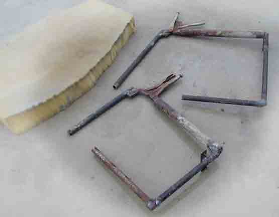
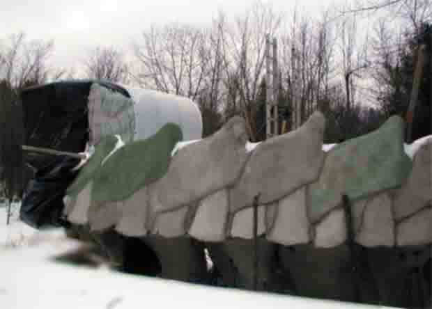
Two pictures above show modified clamps used to hold foam rubber over steep wet tilt cement panels. More pictures will follow eventually.
While the welding wire as a primary reinforcement has excellent characteristics for ferrocement, simple methods of using it remain illusive. Agricultural wire offers much easier use but as a thicker gauge is less ideal than thin gauge welding wire. More effort will be made to show examples, here is a small example for the mean time. Here is another example of simple ringforcement using heavier wire.
Little is known about actual test comparisons between traditional reinforcement,
flat spiral loops and individual "O" rings.
Rings appear to have interesting test possibilities. As a low
budget single handed developer, I have very little opportunity to test the
many ideas
presented in these www pages. The testing cannot keep up with my prototyping
nor my conceptual exploration.
Note: These pages are placed in the public domain and are furnished "as is". The author assumes no responsibility for the use or misuse of the concepts in this series. All authorities should be satisfied first, as might be required, by relevant laws, before any building proceeds.
Searching Synergy .... .... Free Exchange of Ideas
Email comments welcome ~~~~~~~ boa1@pivot.net
Tel : 207 342 5796 . . . (Maine)