We are accustomed to dipole, electromagnetic coils, always bearing one, central, magnetic axis. Here is a simple, experimental coil which apparently differs! It seems to form two orthogonally radial axes! Parallel-coil-turns apparently project magnetic lines radially or orthogonally, from this coil form. Many details follow below. Here are my observations of the unusual, radial magnetic field.
Ordinary coils should vector poles along the axis. However it was found here that specifically folded and paralleled coil turns have apparently expanded upon this old rule. This coil, seems to elaborate on the traditional “Left Hand Rule”. Magnetic poles are said to align magnetic compass needles. I made many observations of my physical model with compasses. Admittedly, the mini compasses, in the photo above, need clearer indicating needles. I clarify my finding in 3D geometry:
The schematic shows the folds where the inner and outer sets of parallel-wire-turns meet. I avoid using the word ‘windings’ because windings have usually referred to continuous coil windings. Instead, we have folded a coil of contiguous windings. We find drawn here, an insulated, split-ring seam indicated by the white space at bottom of this coil. We need to refocus here, on the fact that each-coil-turn folds back upon itself, in parallel, before beginning the next pair of turns. In the above 3D model, (drawing), the lowest two compass indicators have a question mark, to indicate my observation, that the seam alignment can vary, depending upon the positioning of this folded-end seam. As drawn, the open-spot reverses the “seam polarity”, because of the insulated-gap. Whereas very forceful tightening, of the insulted gap, showed that this polarity is somewhat adjustable.
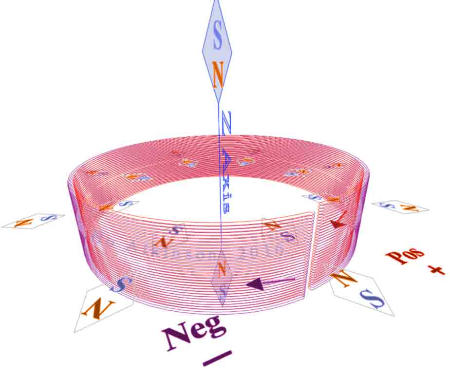
The inside coil-turns are colored red in this 3D-geometry model. The outer coil-turns are purple, (only to aid visualization). All these turns represent a contiguous, inversely-folded, wire coil. I have noted that these effects are dependent upon symmetrical turns... Hurried work resulted in some wrongly crossing turns which spoiled those results, while using (finer) #25AWG. I need to improve my tools. My first radiicoil (earlier photos above), easily folded-up symmetrically, with #20 AWG wire. (See tools further below). My mini-compasses were cheap and some of these failed to point precisely north and south. I chose a set of these mini compasses, which largely agreed in direction.
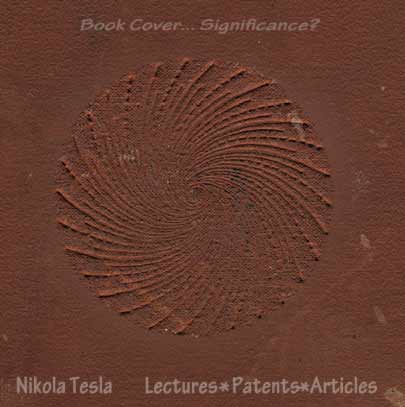
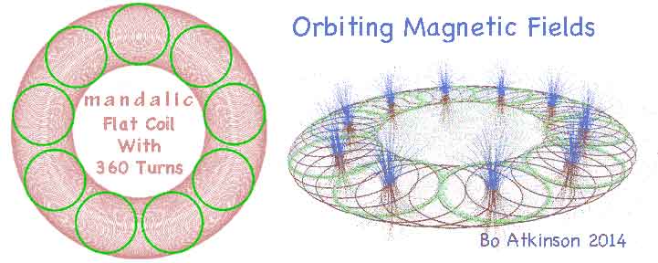
I chose the name “radiicoil”, because the radial vectors are a bold new characteristic. My expectation is that the radial field, may radiate spirally like the symbol from a book cover, pictured above. The spiral might oscillate directionally with alternating current. Next below are some photos of my sportsman’s compass, which show my unusual axial field alignments. (Same coil used as in the first photo, with #20 AWG wire.)
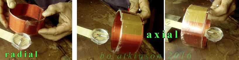
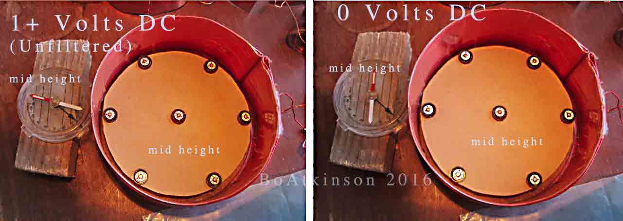
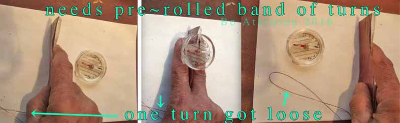
The photo sequence above shows the pass-through of a compass. (Or actually the girdling-past, by the moving coil, with the same effect.) Note how the field defies ordinary axial alignments. The white end of compass needle points to center, at both ends! (Needle reverses if Pos and Neg terminals are reversed). The brown tape holds the folded ends together. These two coil versions were energized with a wall type, un-filtered, DC transformer, (with open circuit at about five volts, closed circuit at about one volt). Next photo below shows the same sort of parallel folded coil, (but with #25 AWG wire), rolled up in snail like spiral fashion. The radial vector is lost in the rolled up versions.
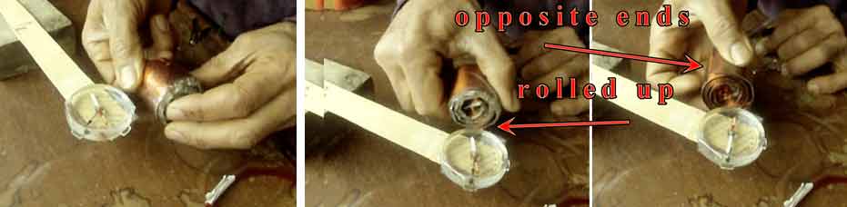
I also tried rolling metal foil, in between… In these rolled up trials, the resulting, axial-only, field alignments were much the same as found with ordinary dipole coils. The radial field was lost. (Note that each end of these rolled up versions possess normal N-S poles, as expected with ordinary coils.) My preliminary conclusion here was that the “parallel radial effect” was cancelled by the continuous roll which laminates layers of doubly-opposing fields, close together. Thus, the “parallel radial effect” cancels itself. I have not tried AC with this rolled up version, instead devoting all my time to the fascinating radial field instead.
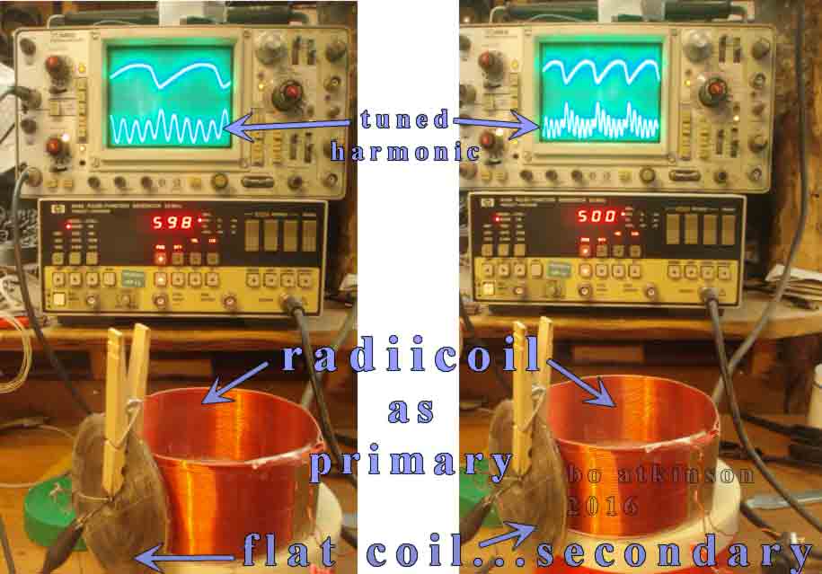
Photo above shows unusual, preliminary trials of one AC effect. The secondary or pick up coil was aligned at various points along the radial plane. (The same radiicoil is used here, as appears in first photo above). I am attracted to harmonic resonance effects, from simple coil geometry, (as contrasted with other sources of harmonics). Coils suggest more-direct interactions with most basic force. In a short time, some good harmonics were noted (in the photo above). Unfortunately, my latest acquisition, (a surplus HP 8116A pulse generator, as used above), came in the mail, partly dysfunctional. (Further explanation is at page bottom).
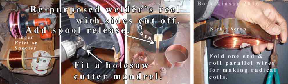
Above Left: Some of the quick methods used to wind the ordinary source coil, (before flattening this ordinary source coil into a flattening band of parallel turns). Needle nose pliers on right are beginning a tight roll, for the #25 AWG, into a snail like spiral, (as seen in photo before oscilloscope photos above). I made just a few tidy coils so far, before focussing on writing this complex webpage. An important technique is to crease and fold just one end at first. Hold the creased end, firmly-straighten and roll from that end only. This method allows the outer band of wires to develop the required, longer, close-fitting circumference wires, (or bands of wires). Once the flattened and folded band is formed into a radiicoil, with two creased ends, it becomes difficult to change the diameter due the creases. So crease with care. Transparent tape was used to hold all paralleled wires in place. Thus, parallel, folded bands fit tightly together without wrinkles. Wrinkles and misaligned bands of wire could otherwise diminish or ruin this effect. The next images suggest induced magnetic fields in the grey color. The brown color represents the radiicoil.
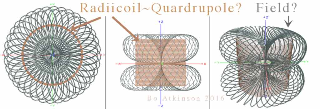
Images Above: Visualizing flows of forces suggest new coil shapes for me to work out physically…. My present focus is on this seemingly unbelievable effect, from a simplistic wire-coil. I had explored doubled-torus geometry years ago, in 3D modeling, but did not expect that a simple coil design could produce so unusual a magnetic field. These field models are based on crude readings. More precise readings will differ somewhat.
Could an ordinary coil compared with a radiicoil, suggest the distinction between paramagnetism and diamagnetism? Regarding Faraday’s chart of magnetic susceptibilities… If an equal length of wire, with equal powering, is used for a regular coil and it produces a stronger magnetic field than does a radiicoil… Could this represent paramagnetic susceptibilities as stronger than are diamagnetic susceptibilities?
Next image below: Without expecting anything like a quadrupole… I had initially expected that both inner and outer magnetic vectors might-possibly flow in the same direction, due to the left hand rule for electromagnets. Instead a surprising radial pole results, from self-opposing poles inside.
Perhaps the outer, longer circumference overpowers an immediate inner circumference which exerts a lesser field. But my last test at the bottom of this webpage actually challenges this reasoning. An additional assumption suggests a diamagnetic field effect upon the diamagnetic copper, according to battery polarity. What ever the rationale, a microscopic view of the magnetics is deserved, before final conclusions are made. Note on drawing above: The single, drawn "C sections" should actually represent multiple turns. My test on actual single turns was not so clear or not immediately so. Radially-bifilar rings seem to have been the unexpected trick all along.
I have been improvising make shift ways to upgrade both hand tools and analytical equipment, to study parallel conductors, in various other geometric layouts. I kept adding brief experiments to compare differing versions of parallel radii in coils, to compare with ordinary coils. Commercially sold, ordinarily adhered, bifilar wire limits the range of parallel-radii, in curved geometries. Parallel circumferences need to differ in length, which stresses the “oo”cross section, (of radial arrangements). This commercial bifilar wire tends to twist annoyingly, during radial coil forming. Therefore experimenters may have reasoned against troubling so much, with paralleled radii, in addition to disqualifying any possibility of a magnetic surprises.
In the image, above, a green wire connects red and blue windings, to complete self opposing coils. My quick winding trials, compared diverse alignments of parallel turns. Multiple, continuous, serial-turns, (connected at the bottom with green wire), test serial versions of diversely paralleled wires. I doubt these are enough turns to determine conclusive effects. Quick trials were made . These arrangement do magnetize uniquely but weakly and therefore uninterestingly, for the moment. (These other coil winding methods are much more work, than my radiicoil production method.) More importantly, the individuated-parallel-radial-turns, if carefully arranged, do seem to magnify the radial field significantly, as compared with the multi-serial-turns, as illustrated just above. Forcing two regular, opposing permanent magnets together, also produces strong radial compass alignments, (but permanent magnets are not practical coils).
Previously known coils, wound as illustrated above, might suggest a radial pole. My very limited first physical trial, with 18 turns resulted with far weaker, almost unnoticeable, radial effects, (on the compass needle). This might indicate a much tighter and weaker swirl of the radial vector. I would like to further experiment with self opposed-winding-coils which posses equal lengths and circumferences. Use better winding equipment. Use good 3D reactive compasses. See what similarities and differences result. I’m thinking that the radiicoil provides a greater range for pulse tuning and pulse shaping, due to individuated turns. ( 'Coil-ettes'?) These concepts and deductions refer to initial trials with low voltage experiments only.
Back to testing the full circle radiicoil in the first photo farther above. One test was full wave AC resonating. With my broken HP 8116A pulse generator, i was able to “sweep” frequencies up through 10 MHz easily. Just pressing the “auto-vernier” buttons sweeps the frequencies consecutively. Resonant peaks come and go. However,further ranging up towards 50MHZ was much more difficult. This was possibly due to my antique 465 Tektronix oscilloscope, possibly due to some missing ranges. Or does my generator suffer upper range glitches as well? I want to be fair with these questions.
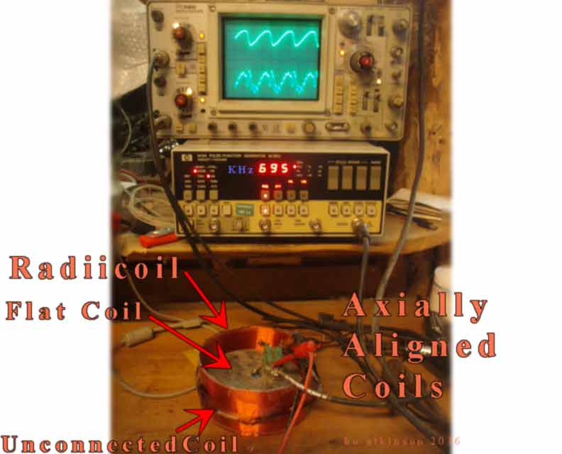
Photo above shows the same radiicoil, as first harmonic photo, except here we have an axially aligned setup. Is there a curious bounce going on where two opposing fields equalize or meet? It will be more interesting to use a function generator with precise pulse shaping functions. I have been slow to read all of Tesla’s available writings, but have begun to wonder if he had used some form of traveling pulse- rings, powered with his vacuum tubes and mercury-based oscillators, but this is going astray from my radiicoil work… In fact, my experiments posted here are all done with low voltages and with weak DC. My radiicoil exhibits little or no visible magnetic pull on crushed, unmagnetized iron, (also, at about 1 volt). Perhaps ordinary compasses are more sensitive than my crushed, iron slag particles. Or what? A diamagnetic electromagnetism? I wonder.
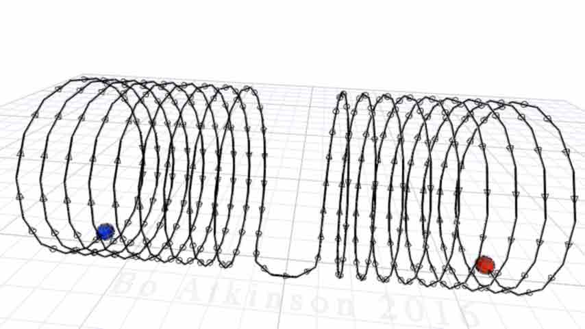
The animated visualization below depicts precise, single turn pulses, passing through an ordinary coil.
This represents an ordinary coil with traveling, energized, pulsed rings, (tuned in frequency). In case these concepts already have a more standard terminology, please let me know, so that i can properly refer to things. I explored differing 3D geometry models for specially shaped pulses, (on other pages of this site). Radially parallel-turns, in coil geometry, modifies waves a bit differently. The radical nature peaks my curiosity. Next below is an additional graphic. It emphasizes individual turns, again, to fit symmetrical, individual pulse segments.
Among my favorite, symmetrically-parallel-coil-ideas is a planar, mandalic version linked here. I postulate that this 2014 coil will orbit dipoles, when properly pulsed with symmetrical pulses. What would it do with radial fields instead of dipole fields? I wonder and wonder keeps me happy.
The link above does not elaborate very much on “self-opposing-dipole-rings”. It does show an option for opposed pulsing, for each turn. I hope this page adds further applicable insights. The radiicoil discussed so far can actually be split wide open, to form a “C” shape or an arc. Curious fields seems to persist or evolve. I explored some possibilities with 3D geometry, besides simple hand held gestures. One would need to further test and continue verifications of these claims, of natural principles, with better test equipment, better tools and with more support for this unusual work.
I have been reading about Tesla’s saga with his ground waves. I was moved to imagine ground waves and air waves interfacing inside one radiicoil. I wondered if he had used opposing field vectors in a coil. His 1894 coil easily self-opposes the pole vectors, while still increasing self capacitance, due to closely positioned negative and positive peaks. Check out the wording in his patent. Has anyone tested this “S version”? (Depicted bellow to the right.)
My lesser coils need much more work. Higher voltage levels, longer windings and magnetic core options all deserve experiments. I tried connecting an 18V LI, (DC) battery to my #20 AWG radiicoil. The coil heated up too quickly, as it dumps too much DC current into 20 AWG copper coils, without the useful reactance of AC power. Still to map out more carefully, is the variable radii effect, obtained by splitting open the seam. Variable radii deserves much closer attention.
It might be worth trying just one very efficient diode on a variable transformer, to sharply space out, 60 or 50 pulsed cycles per second, (no capacitor smoothing). This will more easily allow for higher voltage effects. To quickly and cheaply investigate and inspire more efforts. Junked “step up transformers” from older CRT TVs could provide voltages up to wire insulation limits. Could such transformers be fed by my broken generator? Could this yield new effects? Please let the world know.
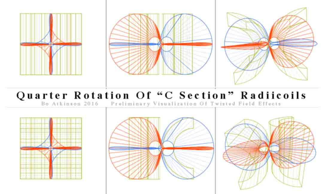
I continue with further visualization of the parallel wound field effects. In example above, two C sections are optionally arranged to begin a geometric contemplation. The 3D model depicts twisted 3D meshes, (as principles of the resulting fields). These are geometrically derived from a symmetrical 2 cycle helix- torus. These models deserve testing with electrified radiicoil c sections, to verify actual field lines. I am trying to inspire experimenters. The next image imagines more progressive, modular kit applications, just in case practical functions, will eventually develop. The following are just wild speculation about uses for specially pulsed coils within imaginary architectural uses.
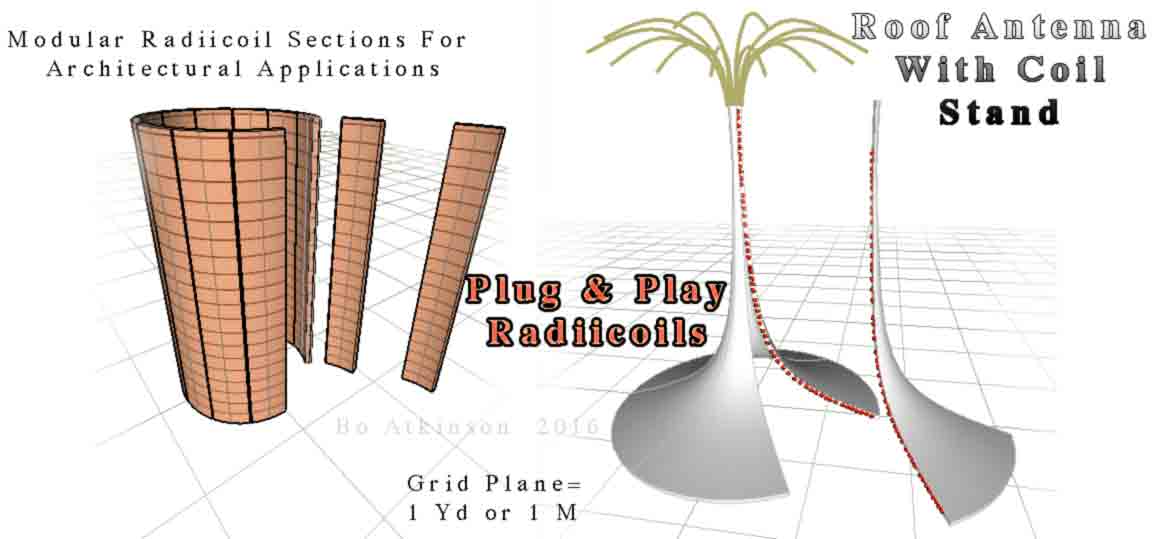
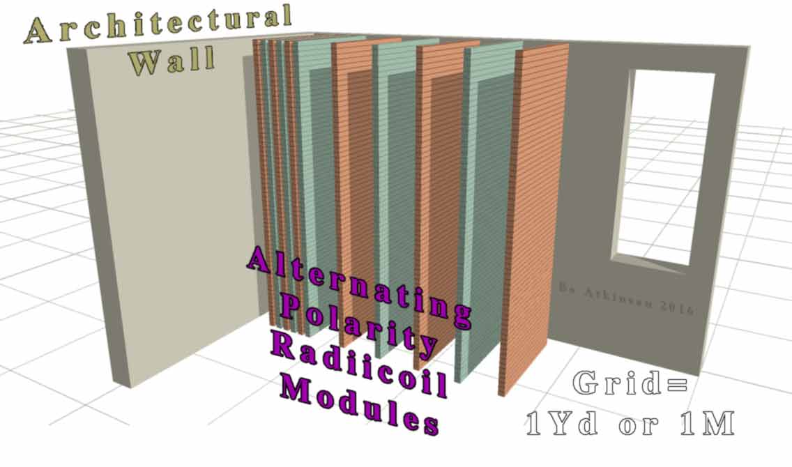
Imaginative applications inspire me to work. The image above on left, suggests modular arced sections, of paralleled, contiguous, inversely-folded, wire bands, but structurally encapsulated. Sections would snap together to complete pre determined circuits. These envision a method to assemble larger and otherwise cumbersome radial coils together. The modular sections on right, suggest assembling a horn like coil. It may provide stability from roof or attic floor plane (inspired by Tesla's “extra coil” along with elevated antenna capacitance). Advantages of installation agility and shipping, do favor this approach of plugging modular kits together. Rectangular modules below, with “rectangularly paralleled turns” might offer other pulsing arrangements. Much larger radiicoils is my fanciful emphasis. Just to inspire continued efforts, in an increasingly turbulent world. Consider the rectangular modules below as coil sections of nearly straight curvature. Consider serial, alternating arrays of modules....
This turns us towards practical testing of segmented radiicoil sections. Next action photos below demonstrate the peculiar field of a “flattened but previously rounded coil”. (I have been hurrying to publish this webpage, while additional ideas continue brain storming.) With initial, expedited testing, generally flattened ordinary coils also challenged the left hand rule! I observe that this level of disarray still provides curious results. I wanted to quickly observe the compass reaction with a flat band of parallel folded wires. I have had enough of hurriedly cobbled together winding setups. So i just re-flattened my #25 AWG coil instead. We need further verifications. Patience. Due to previous rolling up, with tape, the result was a rumpled. Despite the crude un- rolling, (of previously rolled up band), these were the observations, displayed in photos below:
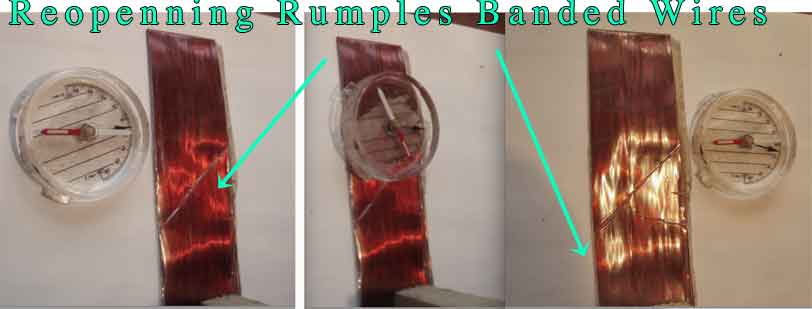
Hand held camera left me just one hand available to steady the band of parallel wires. The compass reading on top of the band (not edge), seemed a little sticky, for the compass needle, (undecided?)… Yet if the needle could align with the rumpled wires, at all, this spurs my curiosity. Otherwise, could it be due to the relative position of the reading taken near to the far end of the band?(December 29 Note: On further testing the compass reading at top of center photo,does align with wires again, but just beyond the end point. I believe that force fields are curved and are not linear like compass needles. Also these particular forces exert very small physical effects.) Flattened wire bands (similar to these photos), seem to suggest extreme coil radii.
All of these tests above, deserve a better experimental settings, using smaller 3D ball compasses. I would rather move onward and fulfill other commitments besides. These crude tests provided me encouragement. December 30 Note: I was asked to make videos and am trying to at least capture some physical reaction. The larger compass has subsequently reversed it's pointer direction and the mini compass pointers are barely visible in videos. If any further insights or updates develop, such as intelligible videos. a potential webpage link waits for it here.
I expect that incremental, symmetrical pulses,will provide more useful effects. The compass readings were closely observed, just to confirm the surprising field trajectories. I'm more interested in testing multiple coil forms and patterned arrays, with incremental, symmetrical pulses.
Various sorts of arrayed radial-axial field effects inspire me. The spherical geo-array or half dome arrays, remind me of Tesla’s half torus antenna style, along with his dome style, as seen in old pictures, of his initial patent and his later thwarted transmitter construction.
{December 31, 2016 Addendum} The seemingly, "magnetically weak field" of the radiicoil and perhaps some other sorts of quadrupole coils, ~(incrementally, symmetrically circuited and pulsed)~ self opposing 'coil-ettes'___ may yet provide a ratcheting interface, to modulate earth resonant standing waves... Or perhaps yet, especially to tap downwards, or to demodulate, a useful resonance, of all local waves, locally... Also to otherwise tune in and to beneficially demodulate and drain away, the locally exasperating, biological-over heating, of currently wasted, rampantly polluting, unhealthy concentrations of emf , (electromotive force), which currently pollutes earth's atmosphere. Tesla researchers somewhat may agree, that so called "air waves" utilized in radio transmission, were and still are a greatly wasted energy resource, when much more benefit could be had with much more benign and globally localizing ground wave modulation and demodulation, of energetic waves, to be transduced from non-local ether. (Perhaps figuratively associated with zero point energy or scalar phenomena).
The Tesla trick all along, may possibly have been to utilize ground waves, to trigger modulation and demodulation, of forms of energy, into currently popular, electrical energy. For an infinitely superior "prime mover" to first be recognized and tapped, for electrical energy obtainment. To inaugurate the use of wiser energy sources, loosely referred to as 'ether', (as inferred by Tesla and earlier scientists). To accomplish this phenomena locally, (everywhere locally) and not to remain reliant upon direct, resistive, line of sight transmission-reception schemes. There has really been no need to reflect radio waves off the ionosphere, nor confine signals or currents inside of closed networks, nor to render the atmosphere electrically-conductive, with geoengineering, aerosol spraying, chem trailing, etc (the action of militant investors who attempt totalitarianism through mind interfacing and soul hijacking, in programs with names like TAM I, SATAN, etc)...All of which additionally poisons life and causes ecocide of an otherwise wonderful planet. As to the big question in one word, why? The natural creation may naturally occur with antitheses at ever junction, (perhaps even up to higher cosmic levels). To naturally play out with predator and parasite, to stimulate human growth, throughout the millennia. To play out the great game of souls. To play out opportunities, for humans to earn higher consciousness, before sovereignty is stolen by demons.
Tesla may have initially been guarding his secrets, to protect his investors. To nurture harmonious trade practices on planet earth. He understood the cunning of predator and parasite. Yet he persisted dutifully, in order to establish a harmonious industrialization. He persisted with his principles until the bitter end. Always to encourage the hopes of an enlightened world. To first demonstrate “free energy for all, anywhere”, to prove via Wardenclyffe, by never exposing the comprehensive master plan, anywhere. (Investors would thereafter profit through commerce of equipment, goods and leases. Rather than through totalitarian mind control objectives, currently destroying planet earth.) As his works became increasingly thwarted in later years, Tesla might have recognized that human cultures were simply too primitive to prioritize love and truth. That the demons of the world needed to self-destruct through treacherous incompetence, all of which our political systems display today… Therefore did he deem it wiser to let his extensive memory ‘files’, his comprehensive design work, to pass out of this world, with his death? Or was the Nazi Skorzeny's confession true, that all of Tesla's best inventions were stolen by Scherf and the modern dark lords of evil? Regardless of such questions, Tesla's legacy has thereby, most powerfully inspired many, to challenge dishonesty, to oppose corruption and to expose the brain washing foisted upon humanity, because of the obvious cover ups in human cultures and cultural histories. Higher consciousness is here to help any, or help us all, to demodulate or to download, bits and pieces of cosmic upgrading, of truer wisdom.
Bo Atkinson 2016
There are too many other good sources to list, except to remind, that word searches easily provide keys for readers, who are ready to unlock realms of knowledge.
I invite comments and independent observations. My purpose here is to share this work through open source mode, before my own coil experiments are continued. Please share these findings! This webpage uses small resolution images to potentially reach wider audiences and to conserve via small bandwidth or to fit small resolutions of mobile screens. Readers are welcome to save and share the whole contents of this page, even to mirror all or parts of my entire website, with authorship intact, please. This may help preserve my own safety. Thank You.
Subtle Energy ~ Bio Energy ~ Self Opposed Windings:
![]() Self Opposed Coil ~ Healing Sculpture
Self Opposed Coil ~ Healing Sculpture
Some of my links for coil art follow below.
Coils For Orbiting Magnetic Fields
InductiveCouplingGeometry.html
Reflex-Vortex-Interleaved.html
HelicalWaveTransverseCoil.html
A tetrahedron is formed as a helix:. Is this the primal tetra helix?.
Pictorial index page of my webpages since the 1990s.
e m a i l . . . write "radiicoil" in subject line, this will get my attention: ![]()
This webpage was first posted on the internet on December 28, 2016. I want to stop editing this page in 2016. Similar findings, prior arts, comments, pro or con might possibly continue at this link.
Some of my pages might have additional links which are to difficult for me to collate. These earlier works are just left in place, for my conceptual record. (I was not able to make selective menu boxes for the whole site. My website software is from the last century. As always, my focus is subject content, when life allows this.)
May one prevail with a harmonious will power.
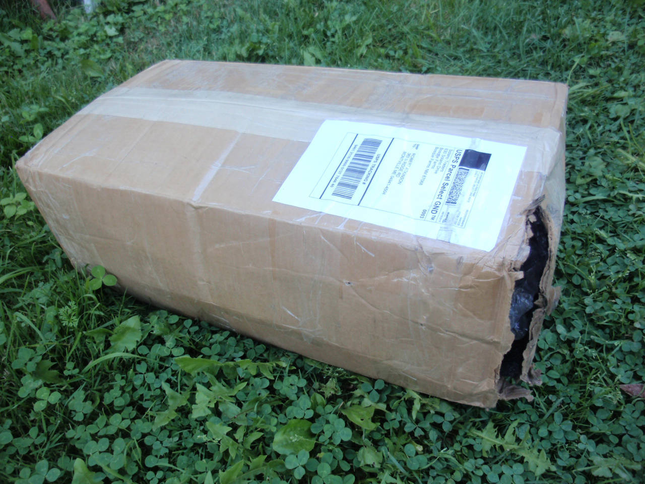
Note on my partly broken function generator: It’s shipping box had been torn open (and it's packaging filler had been partly removed, see next photo below). In my opinion, a delicate terminal (or part) could have been maliciously shocked (or broken) enroute. This particular model was designed with special protection circuitry, but not enough to withstand direct connection of the front panel terminals to full AC line current, an easily achieved prank for immoral perpetrators to do. This function generator was offered as a low cost bargain, from an ebay approved, US source, which alternatively could imply the risk factor with surplus items in general. However, why was the end of the carton and also some internal packing material permanently removed? The delicate instrument was loose to slide around inside. Also, why had it been delayed a long time in the US postal system? Here is a photo of it’s wide open condition, directly after it’s long delayed arrival:
I did not trouble my local post office with complaints. I believe these are good people just doing their job. I accept risks. The surplus vendor and i had opted to save money by avoiding extra (theoretical) insurance. Graciously, the vendor offered a partial refund. (We shared the risk and loss). Unfortunately, my good function generator has lost critical pulse timing, (according to the manual instruction procedures). I wanted to shape the pulses precisely and symmetrically, to advance these experiments much further. I may have to leave this task for better equipped experimenters to consider. Did my many descriptive emails inquiring about function generator specifications and pulse shaping features alert perpetrators? I feel that this is just one small sign of our failing world condition, due to monopolized wars and suppressed technologies. May we heal society? I try to work towards that end.
The content on this website, http://harmoniouspalette.com, is placed in the public domain only as a free exchange of ideas and as a "hard studied wish to serve life". The author assumes no responsibility for the improper use of the concepts in these web pages, as all relevant laws of life and local codes should be verified and observed before any building or experimentation proceeds. Dicussion is welcome, please write. Bo Atkinson